Laser beam centering and pointing system

a laser beam and centering technology, applied in the field of compact, non-invasive optical beam alignment systems, can solve the problems of increasing the complexity of the system, reducing the accuracy of the centering and pointing parameters of the optical beam, and limiting the separation distance between the sensors. the effect of minimizing residual centering and pointing errors

Active Publication Date: 2010-07-29
LAWRENCE LIVERMORE NAT SECURITY LLC
View PDF2 Cites 12 Cited by
  • Summary
  • Abstract
  • Description
  • Claims
  • Application Information

AI Technical Summary

Benefits of technology

[0028]It is another aspect of this invention to provide one or more spatial masks in the form of a programmable amplitude and / or phase pattern which can be updated in real time, thereby optimizing the convergence process temporally and, additionally, minimizing residual centering and pointing errors.
[0029]It is still another aspect of this invention to temporally modulate one or more dynamic spatial masks to provide a set of different reference patterns at the camera plane so that each such reference mask results in an optimal image pattern necessary to more accurately determine the centering and pointing parameters of the optical beam.
[0030]It is further an aspect of this invention to electronically gate, or switch, amongst the reference patterns so that optical interference or deleterious spatial crosstalk effects are minimized so that each pattern can be viewed independently from the other, resulting a centering and pointing measurement with minimal complexity.
[0031]It is another aspect of this invention to generate one or more spatial masks so that the pair of resultant images patterns at the camera plane coherently combines at the camera plane to provide precise interferometric information so that fine-detailed centering and pointing measurements can be determined.
[0032]It is also an aspect of this invention to form a closed-loop system so that the video information at the camera plane can be processed in real-time, where processing algorithms provide spatial pattern information that can be imposed onto the dynamic reference mask, thereby enabling enhanced performance in terms of more precise centering and pointing determination of the incident optical beam, as the fundamental measurement limits of the instrument are approached.

Problems solved by technology

However, situations exist where the separation between the pair of sensors is limited to a small distance.
Moreover, there exist cases where is it highly impractical, and, in other cases, deleterious, to locate one or a pair of optical detectors at different locations within a confined system with a separation distance sufficiently great to determine the spatial location of an optical beam with a specified precision.
The need for a pair of such sensors adds complexity to the system, since two pinholes, two detectors, and, possibly, two beam splitters are required, in addition to optical mounts, fixtures and electronic processors.
These requirements add complexity, cost and weight as well as requiring space for their installation, and, access for their maintenance.
The presence of a pair of separated crosshairs does not permit simultaneous measurements, given the necessity to refocus ones eye or machine vision system, resulting in a greater time to complete the measurement.
As an example, one defocused sight may interfere with the viewer or camera during the time that one attempts to concentrate and focus on the other sight.
Also, since the patterns are fixed in time, the sight geometry may not be optimal during the convergence process.

Method used


Image

  • Laser beam centering and pointing system
  • Laser beam centering and pointing system
  • Laser beam centering and pointing system

Examples


Embodiment Construction

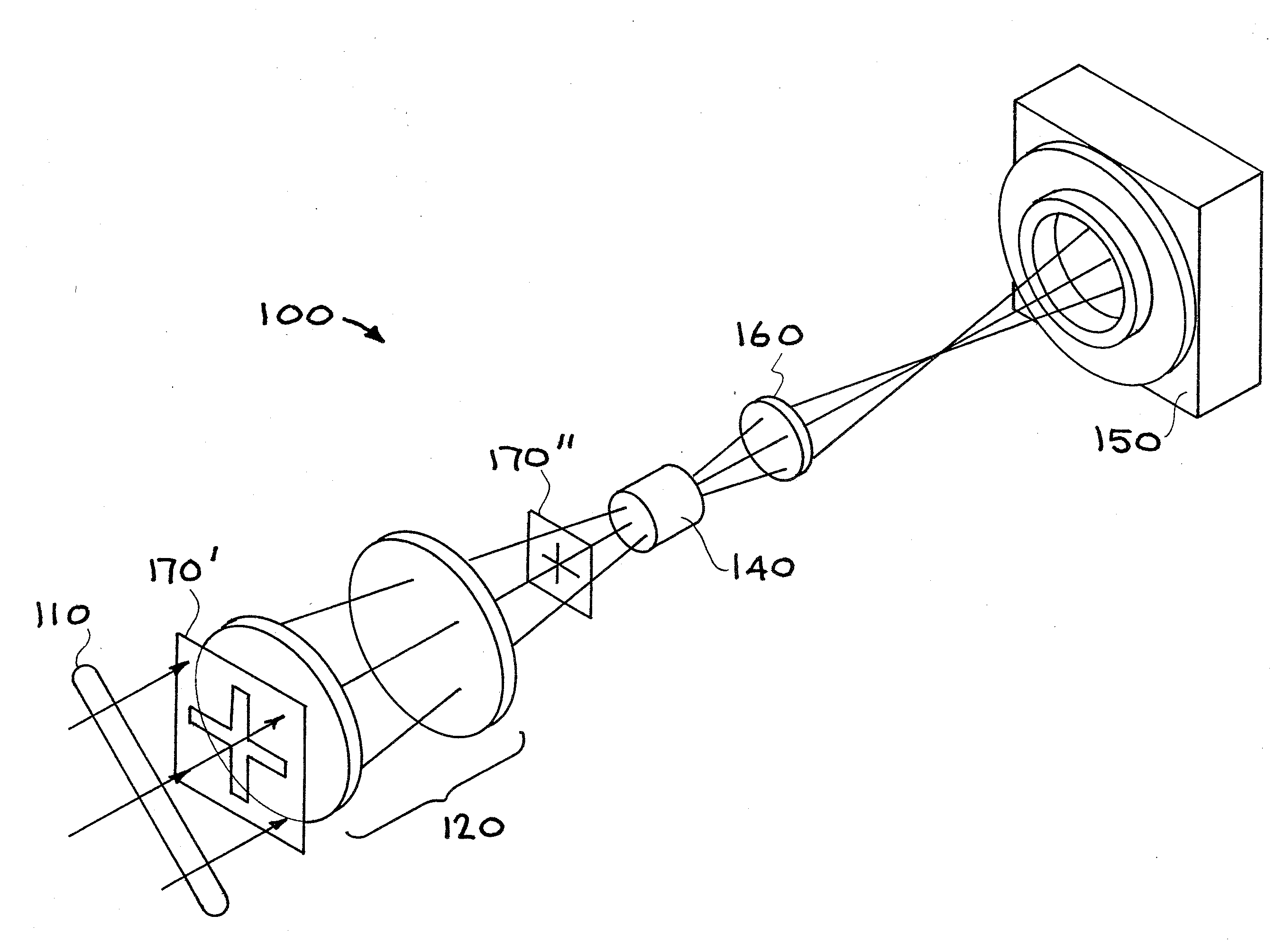
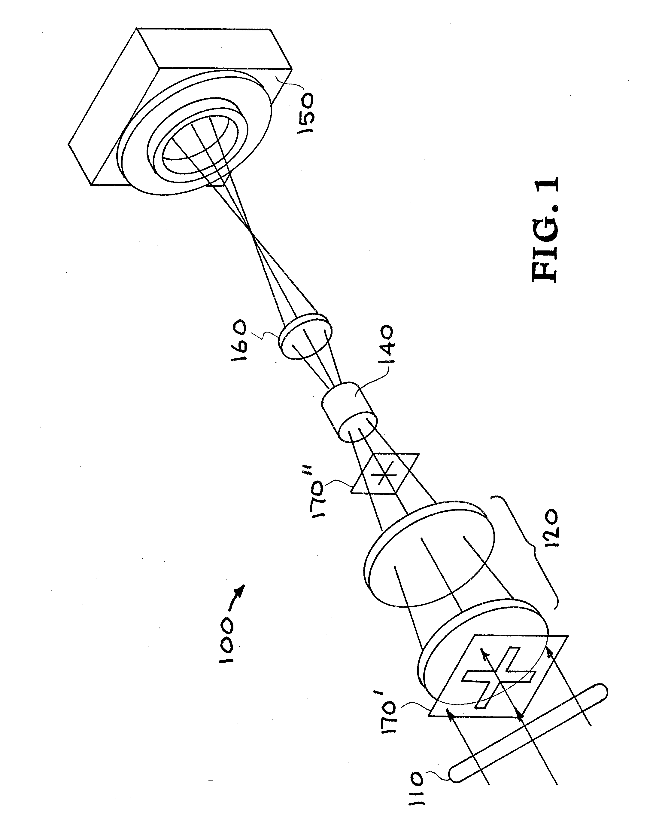
[0042]An exemplary embodiment of a basic optical diagnostic system 100 according to the present invention is shown in FIG. 1. An optical beam 110 is incident upon the system. The goal of the system is to determine the centering and pointing parameters of the beam 110 relative to the diagnostic system 100. The system 100 consists of an objective lens 120 (which is a telephoto lens in some embodiments), an upstream reference pattern 170′ and an intermediate reference pattern 170″, with the former pattern situated directly upstream of the objective lens and the latter pattern situated directly downstream of the objective lens. The upstream reference pattern 170′ serves to provide spatial information necessary to enable precise centering alignment of the incident beam 110 with respect to the apparatus 100. The intermediate reference pattern 170″ provides spatial information necessary to enable precise pointing alignment of the same beam. Downstream of the plane 170″ is a bi-focal lens 1...


PUM


Abstract

An optical instrument aligns an optical beam without the need for physical intervention of the instrument within the apparatus or platforms from which the trajectory of the beam to be ascertained. The alignment apparatus and method enable the desired function to be realized without the placement of physical apertures or sensors directly in the path of the beam through the system whose spatial position and slope is to be sought. An image plane provides the observer with a pair of well-defined images that are indicative of the beam centering and pointing alignment parameters. The optical alignment can be realized without the need for referencing to an external or fixed set of coordinates or fiducials. The instrument can therefore service situations where adverse environments would otherwise prohibit the use of such instruments, including regions of high radiation, high temperature, vacuum and/or cryogenic atmospheres.

Description

CROSS-REFERENCE TO RELATED APPLICATIONS [0001]This application claims the benefit of U.S. Provisional Patent Application No. 61 / 148,243 titled “Centering and Pointing System,” filed Jan. 29, 2009, the disclosure of which is hereby incorporated herein by reference.STATEMENT REGARDING FEDERALLY SPONSORED RESEARCH OR DEVELOPMENT [0002]The United States Government has rights in this invention pursuant to Contract No. DE-AC52-07NA27344 between the United States Department of Energy and Lawrence Livermore National Security, LLC.BACKGROUND OF THE INVENTION[0003]1. Field of the Invention[0004]The present invention relates to optical beam alignment systems, and more specifically, it relates to compact, non-invasive optical beam alignment systems for centering and pointing of an optical beam from a remote location.[0005]2. Description of Related Art[0006]Devices to align an optical beam in space are well known in the art. The prior art in the area of optical beam alignment typically requires ...

Claims


Application Information

Patent Timeline
Patent Type & Authority Applications(United States)
IPC IPC(8): G01B11/14
CPCG01B11/272
Inventor RUSHFORD, MICHAEL CHARLES
Owner LAWRENCE LIVERMORE NAT SECURITY LLC
Why Eureka
Try Eureka