System and method for clock jitter compensation in direct RF receiver architectures

a receiver architecture and clock jitter compensation technology, applied in the field of direct radio frequency (rf) receiver architectures, can solve the problems of clock jitter associated with rf, significant reduction of snr, nyfr can suffer from clock jitter, etc., and achieve the effect of improving the performance of direct radio frequency (rf) receivers

Inactive Publication Date: 2010-07-29
L 3 COMM INTEGRATED SYST
View PDF25 Cites 11 Cited by
  • Summary
  • Abstract
  • Description
  • Claims
  • Application Information

AI Technical Summary

Benefits of technology

[0010]The systems and methods disclosed herein provide clock jitter compensation architectures that improve the performance of direct radio frequency (RF) receivers. These disclosed clock jitter compensation architectures advantageously inject a high frequency tone into the received radio frequency (RF) signals in order to help identify and then compensate for the clock jitter noise. After injecting the tone, the jitter noise going through the direct RF bandpass sampling receiver is estimated using a narrow bandwidth filter. This estimation technique is possible because the jitter noise is not white noise, but is actually shaped, as described in more detail below, and because all signals have the same induced jitter phase modulation with only an integer scale factor on the jitter phase varying with Nyquist zone. After the jitter noise is estimated, the received signals are further processed and demodulated similar to the modulation / demodulation used for Nyquist folded receivers (NYFR), where the modulation / demodulation depends on the Nyquist zone of the received signal. With respect to the clock jitter compensation architectures, the relative modulation factor for the modulation is computed and then applied to the Nyquist zone to de jitter that particular Nyquist zone (i.e., to simultaneously de jitter all signals from a given Nyquist zone). Other features and variations can be implemented, as desired, and a related methods and systems can be utilized, as well.

Problems solved by technology

One limitation of this architecture, however, is that for very high RF input signals and operational conditions, the RF Sample Clock 212 jitter is amplified and may result in subsequent signal distortion in the form of signal spreading in the output signals, leading to significantly reduced SNR.
As with the RDRFBSR, the NYFR can suffer from clock jitter associated with the RF sampling.
As indicated above, the RDRFBSR and NYFR architectures can suffer from clock jitter due to the direct RF sampling.
Improved solutions, however, are needed, as these techniques are limited in applicability, difficult to implement, and are computationally expensive.

Method used


Image

  • System and method for clock jitter compensation in direct RF receiver architectures
  • System and method for clock jitter compensation in direct RF receiver architectures
  • System and method for clock jitter compensation in direct RF receiver architectures

Examples


Embodiment Construction

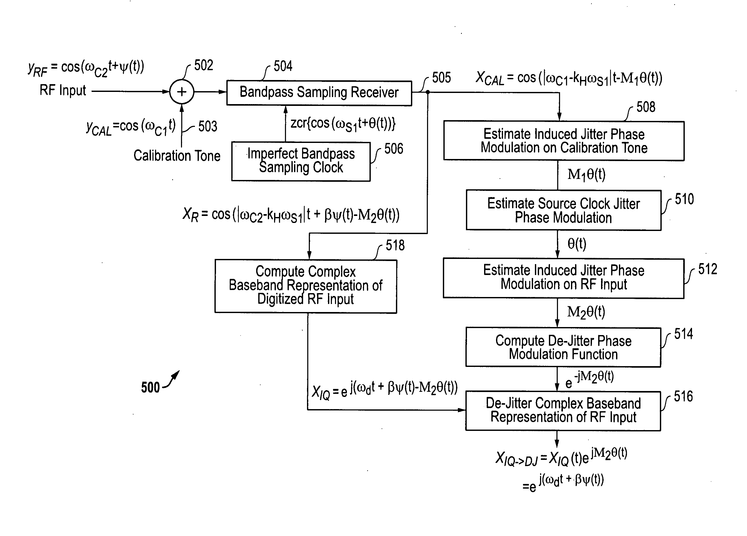
[0023]The systems and methods disclosed herein provide clock jitter compensation architectures that improve the performance of direct radio frequency (RF) receivers. For these clock jitter compensation architectures, a high frequency tone is injected into the receive radio frequency (RF) signals to allow the clock jitter noise to be identified and compensated for in the output signals provided by the receiver.

[0024]It is noted that the clock jitter compensation architectures described herein relate to spur reduction architectures described in U.S. Provisional Patent Application Ser. No. 61 / 203,115 filed Dec. 18, 2008 and in the concurrently filed U.S. patent application Ser. No. ______ entitled “SYSTEM AND METHOD FOR IMPROVED SPUR REDUCTION IN DIRECT RF RECEIVER ARCHITECTURES” by Fudge et al., each of which is hereby incorporated by reference in its entirety. As indicated above, the clock jitter compensation architectures described herein are also related to the receiver architectur...


PUM


Abstract

Systems and methods that provide clock jitter compensation architectures that improve the performance of direct radio frequency (RF) receivers by injecting a calibration tone into the received radio frequency (RF) signals in order to help identify and then compensate for the clock jitter noise. After injecting the tone, the jitter noise going through the direct RF bandpass sampling receiver is estimated using a narrow bandwidth filter, and the received signals are further processed and demodulated depending on the Nyquist zone of the received signal. The relative modulation factor for the modulation is computed and then applied to the Nyquist zone to de jitter that particular Nyquist zone.

Description

[0001]The present application claims priority to co-pending U.S. provisional patent application Ser. No. 61 / 203,114 filed Dec. 18, 2008 and entitled “SYSTEM AND METHOD FOR CLOCK JITTER COMPENSATION IN DIRECT RF RECEIVER ARCHITECTURES”, by Fudge et al., the disclosure of which is incorporated herein by reference in its entirety.RELATED APPLICATIONS[0002]The present provisional application is related in subject matter to concurrently filed patent application Ser. No. ______ entitled “SYSTEM AND METHOD FOR IMPROVED SPUR REDUCTION IN DIRECT RF RECEIVER ARCHITECTURES” by Fudge et al., which is incorporated herein by reference in its entirety, and to Provisional Patent Application Ser. No. 61 / 203,115 filed Dec. 18, 2008 and entitled “SYSTEM AND METHOD FOR IMPROVED SPUR REDUCTION IN DIRECT RF RECEIVER ARCHITECTURES”, by Fudge et al., which is also incorporated herein by reference in its entirety.TECHNICAL FIELD OF THE INVENTION[0003]This invention relates to receiver and transmitter archit...

Claims


Application Information

Patent Timeline
Patent Type & Authority Applications(United States)
IPC IPC(8): H04L7/00
CPCH04L7/0083H04B1/28
Inventor FUDGE, GERALD L.CHIVERS, MARK A.RAVINDRAN, SUJITYEH, ALEX
Owner L 3 COMM INTEGRATED SYST
Why Eureka
Try Eureka