Fuel cell stack

a fuel cell and stack technology, applied in the direction of fuel cells, cell components, fuel cell details, etc., can solve the problems of insufficient strength of discharge pipes, short circuit between metal members through liquid, and laborious piping operation, so as to achieve the desired power generation performance, prevent short circuit through liquid, and simple and compact structure

Active Publication Date: 2010-07-29
HONDA MOTOR CO LTD
View PDF8 Cites 7 Cited by
  • Summary
  • Abstract
  • Description
  • Claims
  • Application Information

AI Technical Summary

Benefits of technology

[0012]A main object of the present invention is to provide a fuel cell stack having simple and compact structure in which it is possible to reliably prevent short-circuiting through liquid, and maintain the desired power generation performance.
[0018]According to the present invention, the reactant gas discharged from the reactant gas discharge passage to the reactant gas outlet flows through the electrically insulating pipe, and then, the reactant gas is supplied to the humidifier or the water-containing reactant gas inlet of the reactant gas circulation apparatus. The water-containing reactant gas inlet has the inclined channel inclined upwardly in a direction away from the reactant gas outlet. Therefore, the water component in the reactant gas supplied to the water-containing reactant gas inlet moves toward the reactant gas outlet along the slope of the inclined channel easily.
[0019]In the structure, electrically insulating pipe at least extends up to an end of the inclined channel where inclination of the inclined channel is started. Therefore, the water is not retained at the water-containing reactant gas inlet, and no electrically conductive path (short-circuiting through liquid) connecting the inside to the outside of the fuel cell stack through the electrically conductive portion is formed. With simple and compact structure, it becomes possible to suitably prevent short-circuiting through liquid from the fuel cell stack.
[0020]Further, according to the present invention, the reactant gas discharged from the reactant gas discharge passage to the reformer partially flows into the gap between the outer circumference of the electrically insulating pipe and the inner wall of the humidifier joint. In the structure, it is possible to prevent liquid droplets from being retained at the reaction gas ejection port of the electrically insulating pipe, and prevent continuation of liquid through the retained water to the humidifier joint.
[0021]Therefore, no electrically conductive path (short-circuiting through liquid) connecting the inside to the outside of the fuel cell stack through the electrically conductive portion is formed. With simple and compact structure, it becomes possible to suitably prevent short-circuiting through liquid from the fuel cell stack, and maintain the desired power generation performance.

Problems solved by technology

As a result, short-circuiting may occur between the metal members through the liquid, i.e., the condensed water.
However, since the discharge pipes 4b, 5b are made of electrically insulating material, if the discharge pipes 4b, 5b are elongated, the strength of the discharge pipes 4b, 5b may become insufficient.
Further, the piping operation may become laborious, and the pipe structure may have a large scale.

Method used


Image

  • Fuel cell stack
  • Fuel cell stack
  • Fuel cell stack

Examples


first embodiment

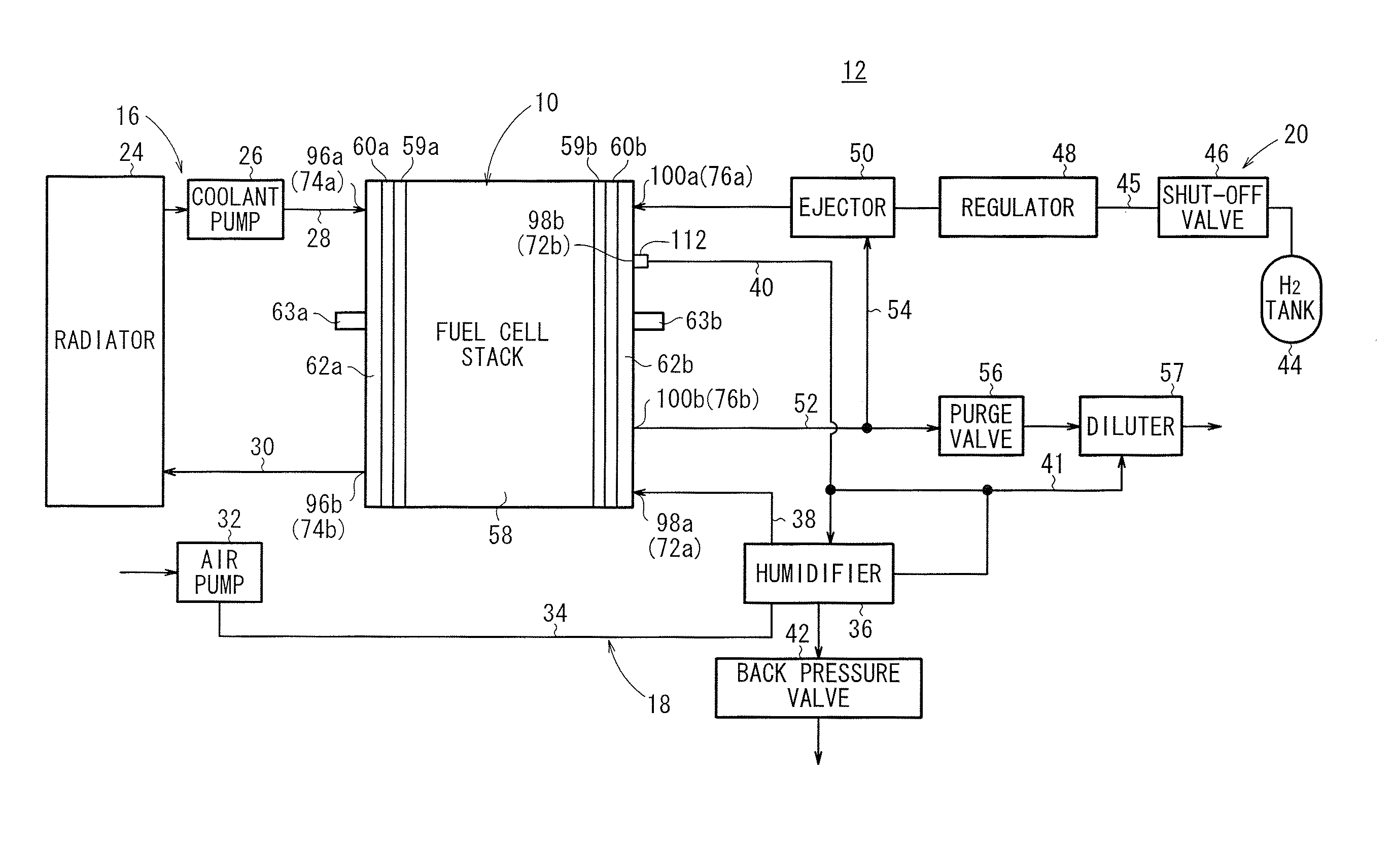
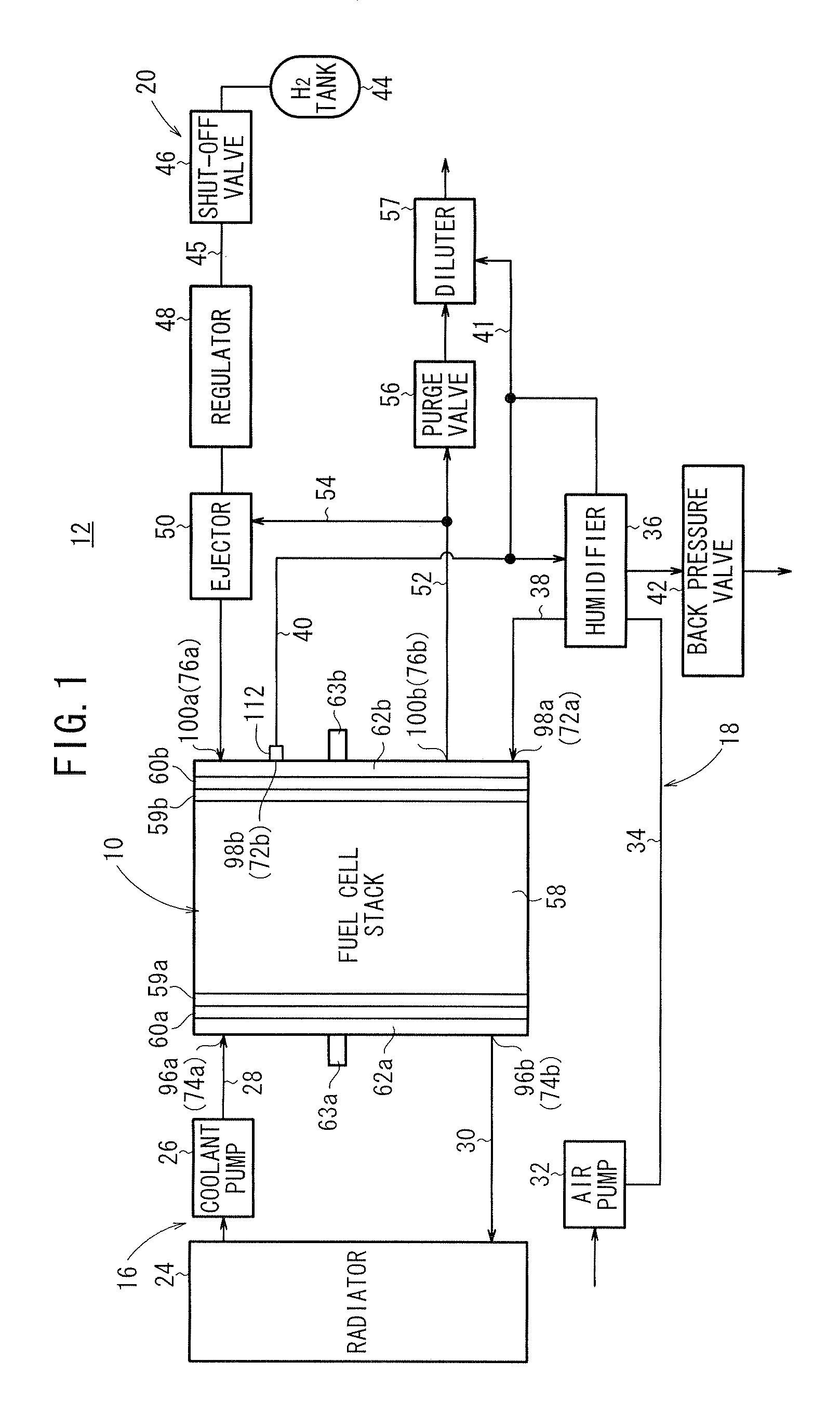
[0036]In FIG. 1, a fuel cell system 12 including a fuel cell stack 10 according to the present invention is mounted in a fuel cell vehicle (not shown). The fuel cell system 12 includes the fuel cell stack 10, a coolant supply mechanism 16 for supplying a coolant to the fuel cell stack 10, an oxygen-containing gas supply mechanism 18 for supplying an oxygen-containing gas (reactant gas) to the fuel cell stack 10, and a fuel gas supply mechanism 20 for supplying a fuel gas (reactant gas) to the fuel cell stack 10.

[0037]The coolant supply mechanism 16 includes a radiator 24. The radiator 24 is connected to a coolant supply pipe 28 through a coolant pump 26, and connected to a coolant discharge pipe 30.

[0038]The oxygen-containing gas supply mechanism 18 includes an air pump 32. One end of an air supply pipe 34 is connected to the air pump 32, and the other end of the air supply pipe 34 is connected to a humidifier 36. The humidifier 36 is connected to the fuel cell stack 10 through a hu...

second embodiment

[0080]FIG. 7 is a diagram schematically showing structure of a fuel cell system 132 including a fuel cell stack 130 according to the present invention.

[0081]The constituent elements that are identical to those of the fuel cell system 12 according to the first embodiment are labeled with the same reference numerals, and description thereof will be omitted. Also in third or further embodiments as described later, the constituent elements that are identical to those of the fuel cell system 12 according to the first embodiment are labeled with the same reference numerals, and description thereof will be omitted.

[0082]A fuel gas circulation apparatus (reactant gas circulation apparatus) 134 is attached to the fuel cell stack 130. The fuel gas circulation apparatus 134 includes a gas-liquid separator 136 attached to the fuel gas outlet 100b of the end plate 62b, and the ejector 50 connected to the gas-liquid separator 136 through the return pipe 54.

[0083]A resin coupling pipe 110 is attac...

third embodiment

[0087]FIG. 8 is a cross sectional view showing main components of a fuel cell stack 140 according to the present invention.

[0088]The fuel cell stack 140 includes a resin pipe 142 connecting the end plate 62b and the humidifier joint 101. A gap S is formed between the outer circumference of the other end 142b of the resin pipe 142 having a small diameter and the inner wall of the humidifier joint 101 (see FIGS. 8 and 9). Part of the off gas flows through the gap S. The cross sectional area in the opening of the off gas ejection port 116 is smaller than the channel cross sectional area in the other end 142b of the resin pipe 142.

[0089]At the lowermost end of the outer circumference of the other end 142b, a drain hole 144 is formed in a predetermined direction, e.g., in a direction of gravity. The drain hole 144 is connected to a water drainage chamber 122 of the humidifier joint 101, and the water drainage chamber 122 is connected from the dilution channel 41 to the diluter 57 through...


PUM

PropertyMeasurementUnit
electrically insulatingaaaaaaaaaa
electricallyaaaaaaaaaa
circumferenceaaaaaaaaaa

Abstract

An end plate of a fuel cell stack is directly fixed to a humidifier. A resin pipe is attached to an oxygen-containing gas outlet of an end plate through a resin coupling pipe. The resin pipe includes one end having a large diameter and the other end having a small diameter. The other end is provided at an off gas supply channel of the humidifier. The off gas supply channel includes an inclined channel. The other end extends up to an end of the inclined channel where inclination of the inclined channel is started. An off gas ejection port is formed at the other end. The off gas ejection port is opened to the end of the inclined channel where inclination is started. Condensed water returned along the inclined channel flows from the off gas ejection port into the resin pipe.

Description

CROSS-REFERENCE TO RELATED APPLICATION[0001]This application is based upon and claims the benefit of priority from Japanese Patent Applications No. 2009-014447 filed on Jan. 26, 2009 and No. 2009-218892 filed on Sep. 24, 2009, in the Japan Patent Office, of which the contents are incorporated herein by reference.BACKGROUND OF THE INVENTION[0002]1. Field of the Invention[0003]The present invention relates to a fuel cell stack formed by stacking a plurality of power generation cells in a stacking direction. A reactant gas discharge passage extends through the fuel cell stack for allowing a reactant gas after partially consumed in power generation reaction to flow through the reactant gas discharge passage in the stacking direction. An end plate is provided at one end of the fuel cell stack in the stacking direction, and a humidifier connected to the reactant gas discharge passage is attached to the end plate.[0004]2. Description of the Related Art[0005]For example, a solid polymer ele...

Claims


Application Information

Patent Timeline
Patent Type & Authority Applications(United States)
IPC IPC(8): H01M2/00
CPCH01M8/02H01M8/0247Y02E60/50H01M8/241H01M8/2465H01M8/04126H01M8/0267H01M8/0258H01M8/2485H01M8/2483
Inventor MIYAJIMA, KAZUYOSHISUZUKI, MASAHARUIITAKA, SATOSHINAITO, HIDEHARUHIDAKA, YOHEIFUJIWARA, SOFUKUI, KAORUMATSUTANI, MASAHIROYOSHINAGA, NARIYUKI
Owner HONDA MOTOR CO LTD
Why Eureka
Try Eureka