
Apparatus and method for arthroscopic transhumeral rotator cuff repair

a transhumeral rotator cuff and arthroscopic technology, applied in the field of surgical devices and methods for repair of torn tissue, can solve the problems of plurality of screws, particularly bothersome rotator cuff injuries, and high cost of the procedur

Active Publication Date: 2010-07-29
BIOMET MFG CORP
View PDF52 Cites 24 Cited by
  • Summary
  • Abstract
  • Description
  • Claims
  • Application Information

AI Technical Summary

Benefits of technology

[0009]It is therefore an object of the present invention to provide an apparatus and method for repair of torn rotator cuff tissue wherein sutures are anchored along the far cortex of the bone thereby bypassing the cancellous bone mass.
[0010]It is yet another object of the present invention to provide an apparatus and method in which the procedure can be conducted in a minimally invasive manner by minimizing the number of suture passes through the soft tissue, yet ensuring that the sutures are suitably anchored in both a far bone anchor point, as well as a near anchor point in the soft tissue surrounding the rotator cuff.
[0011]It is yet another object of the present invention to provide an apparatus and method in which a drill guide can be used to precisely locate bone tunnels to be drilled, and the drill guide is easily adaptable for use with patients of differing sizes.
[0012]It is yet another object of the present invention to generally simplify the surgical procedure of a repairing a torn rotator cuff repair in which not only is the amount of implanted hardware reduced, but also the procedure is simplified by minimizing the surgical tools required to conduct the procedure.
[0017]In yet another aspect of the present invention, a particularly advantageous self-anchoring suture is provided. This self-anchoring suture incorporates a dispersed pattern of protuberances or beads that can be passed in a specified direction through the bone tunnel but prevent pullout by force applied in the opposite direction.

Problems solved by technology

Rotator cuff injuries are particularly bothersome in that the torn tendons must be highly stabilized in order for healing to occur.
Although increasing the number of anchors used in the procedure can result in improved healing, there are also a number of drawbacks associated with the increased use of anchors, most notably, the cost of the procedure.
One particular disadvantage with this known type of rotator cuff repair is that the plurality of screws is secured within the cancellous bone mass beneath the near cortex of the head of the humerus.
This bone mass in the humerus head is particularly susceptible to osteopenic degradation in which the bone density can significantly diminish, particularly in older patents.
Accordingly, anchors placed in this degraded cancellous bone mass do not remain stationary, and some degree of pullout or loosening will occur, thereby preventing proper healing of the tendon tissue to the bone.
Although the drill guides of these prior art references are well known for arthroscopic repair of knee tendons, these drill guides have been limited to use with the knee joint, and have not been used as drill guides for other joints.

Method used


Image

  • Apparatus and method for arthroscopic transhumeral rotator cuff repair
  • Apparatus and method for arthroscopic transhumeral rotator cuff repair
  • Apparatus and method for arthroscopic transhumeral rotator cuff repair

Examples


Embodiment Construction

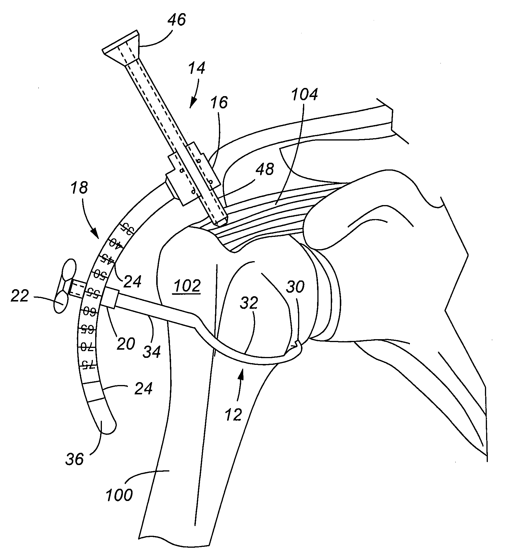
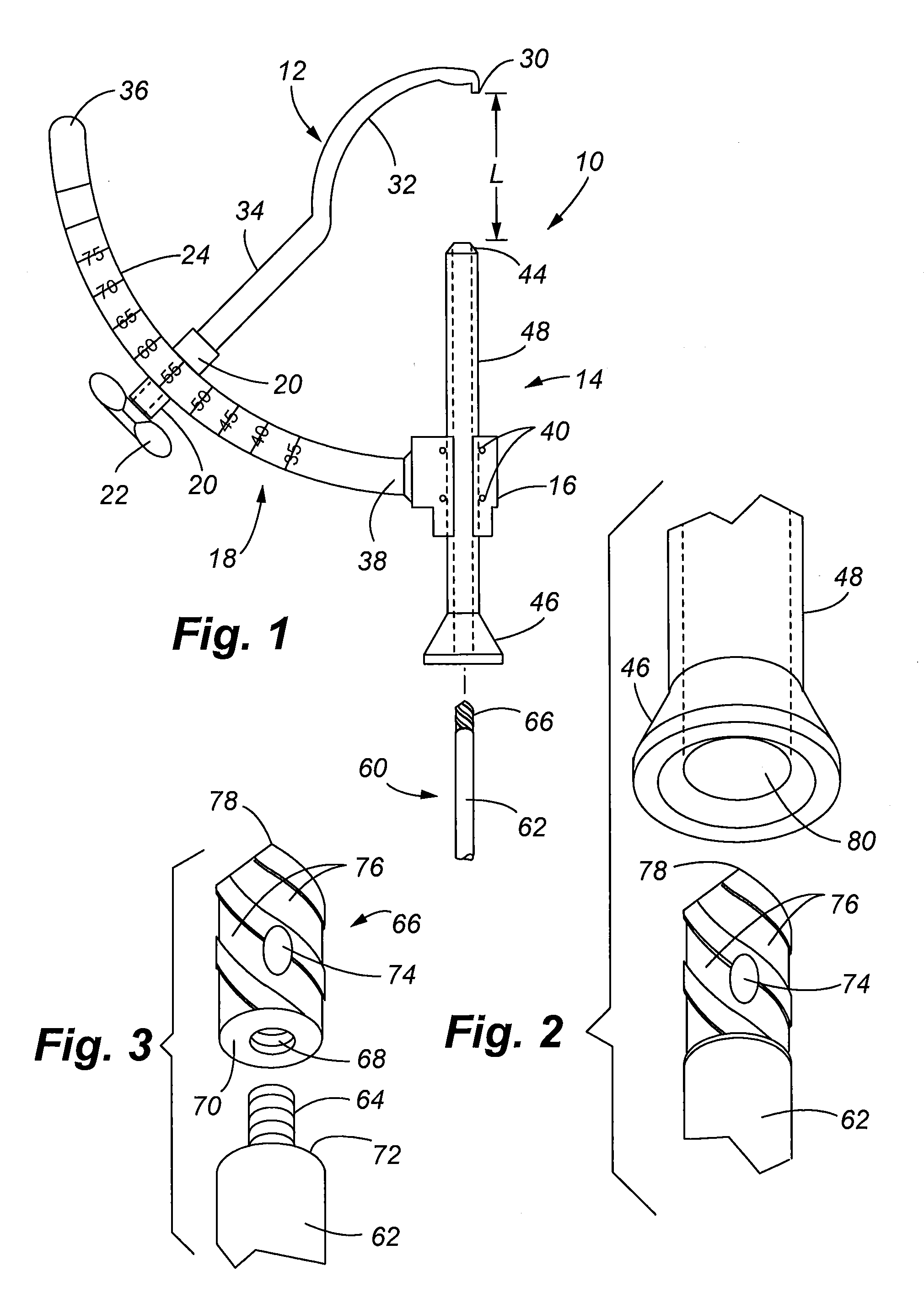
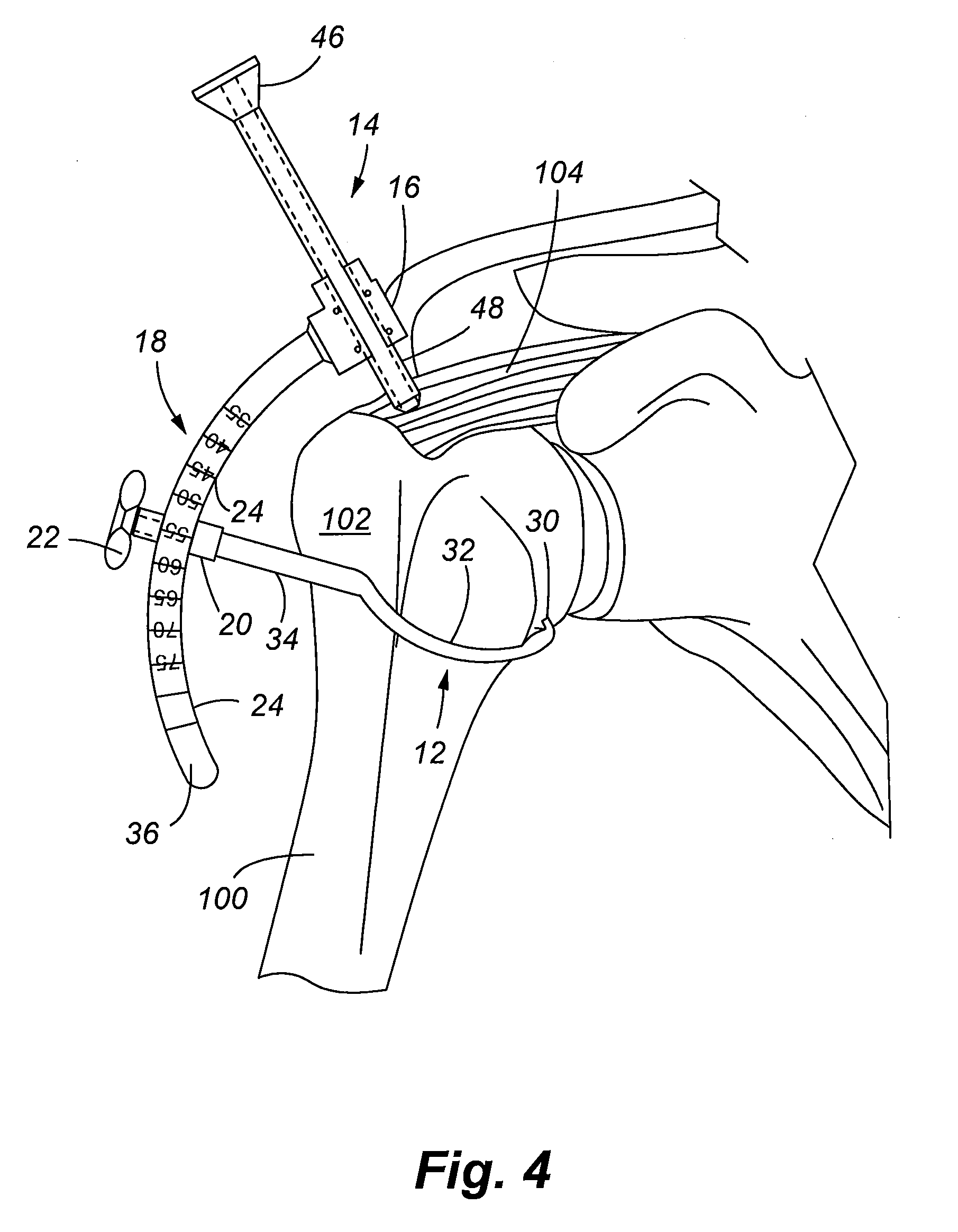
[0047]Referring to FIG. 1, the drill guide assembly 10 of the present invention is illustrated. The drill guide assembly includes a marking hook 12, a drill guide 14, and an angle setting arm 18. The angle setting arm 18 is secured to one lateral side of a drill guide mount 16. The drill guide 14 is received longitudinally through the drill guide mount 16 and is secured through an open slot in the drill guide mount as by a plurality of set screws 40. The marking hook 12 is secured to the angle setting arm 18 by a marking hook mount 20 which is received at a selected slidable location along the angle setting arm 18. A fastener, such as a wing nut or screw 22 tightens the marking hook mount 20 to a selected angular location along the angle setting arm 18. A plurality of angular gradations 24 are marked along the angle setting arm 18 that assists a practitioner in setting the correct location for the marking hook 12. More specifically, a practitioner must determine the length L of the ...


PUM


Abstract

Apparatuses and methods are provided for arthroscopic rotator cuff repair incorporating a transhumeral bone tunnel. The apparatus comprises a number of components that can also be considered a repair system to include a drill guide, a marking hook, and a drill with a removable tip that serves as a bone anchor. In another aspect, the invention provides a suture especially adapted for securing both soft tissue and bone anchors that reduces forces transmitted to the anchors by secondary anchoring of the suture within the bone tunnel based on the geometry of the anchor. In additional aspects of the invention, the components of the drill guide assembly comprise a cannulated marking hook and a drill guide with multiple bores. In additional aspects of the invention, an implantable bone anchor is provided that is especially adapted for placement through a bone tunnel, and wherein the implantable anchor is collapsible to increase the effective size of the anchor for securing the anchor to the far side opening of the bone tunnel through which the anchor was placed. Methods of the invention include a method of arthroscopic repair of a rotator cuff, and methods of activating an implantable anchor.

Description

FIELD OF THE INVENTION[0001]The present invention relates to surgical devices and methods for repair of torn tissue, and more particularly, to an apparatus and method for repair of a damaged rotator cuff by transhumeral suture anchoring in an arthroscopic procedure.BACKGROUND OF THE INVENTION[0002]Rotator cuff injuries are a very common injury suffered by patents of all ages. A torn rotator cuff typically requires a surgical procedure to reattach the torn tendons to the bone of the humeral head. Rotator cuff injuries are particularly bothersome in that the torn tendons must be highly stabilized in order for healing to occur.[0003]In recent years, the preferred solution to ensure proper healing of a rotator cuff is to increase the number of anchors used to secure the torn tissue to the bone. Although increasing the number of anchors used in the procedure can result in improved healing, there are also a number of drawbacks associated with the increased use of anchors, most notably, th...

Claims


Application Information

Patent Timeline
IPC IPC(8): A61B17/58A61B17/00A61B17/04
CPCA61B17/0401A61B17/0469A61B17/0482A61B17/0485A61B17/1617A61B17/1684A61B2017/1778A61B2017/00986A61B2017/0404A61B2017/0414A61B2017/0417A61B2017/0464A61B17/1714A61B17/1778
Inventor SCHNEIDER, DAVID JAMES
Owner BIOMET MFG CORP
Learn More