Isolation circuitry and method for hiding a power consumption characteristic of an associated processing circuit

a technology of isolation circuits and power consumption characteristics, applied in the direction of electric variable regulation, process and machine control, instruments, etc., can solve the problems of consuming a significant amount of power for no useful purpose, a relatively small amount of voltage drop across the capacitor, and subsequent charging processes. achieve the effect of significant flexibility

Active Publication Date: 2010-08-05
RGT UNIV OF MICHIGAN
View PDF7 Cites 16 Cited by
  • Summary
  • Abstract
  • Description
  • Claims
  • Application Information

AI Technical Summary

Benefits of technology

[0021]Hence, it will be appreciated that the isolation circuitry of the present invention is more effective at protecting the processing circuitry from DPA techniques, whilst also consuming significantly less power than the known prior art techniques.
[0022]In one embodiment, the isolation circuitry further comprises discharge tuning circuitry placed in series with said third switch across said capacitor, the discharge tuning circuitry being responsive to a control signal from the control circuitry to enable the rate of discharge of the capacitor during the active state of the third switch to be varied. Such an approach provides significant flexibility, since it enables the same isolation circuitry to be used with a variety of different processing circuits, which may for example operate at different speeds. Dependent on the operating speed of the processing circuit, the discharge tuning circuit enables the rate of discharge of the capacitor to be sped up or slowed down as required, without needing to change the duration of the active state of the third switch.

Problems solved by technology

However, during the use phase where the capacitor is used to power the processing device, the voltage will drop by a relatively small amount.
Hence, during the subsequent discharge phase, a significant voltage drop across the capacitor takes place, with the subsequent charging process then consuming a significant amount of power for no useful purpose.

Method used


Image

  • Isolation circuitry and method for hiding a power consumption characteristic of an associated processing circuit
  • Isolation circuitry and method for hiding a power consumption characteristic of an associated processing circuit
  • Isolation circuitry and method for hiding a power consumption characteristic of an associated processing circuit

Examples


Embodiment Construction

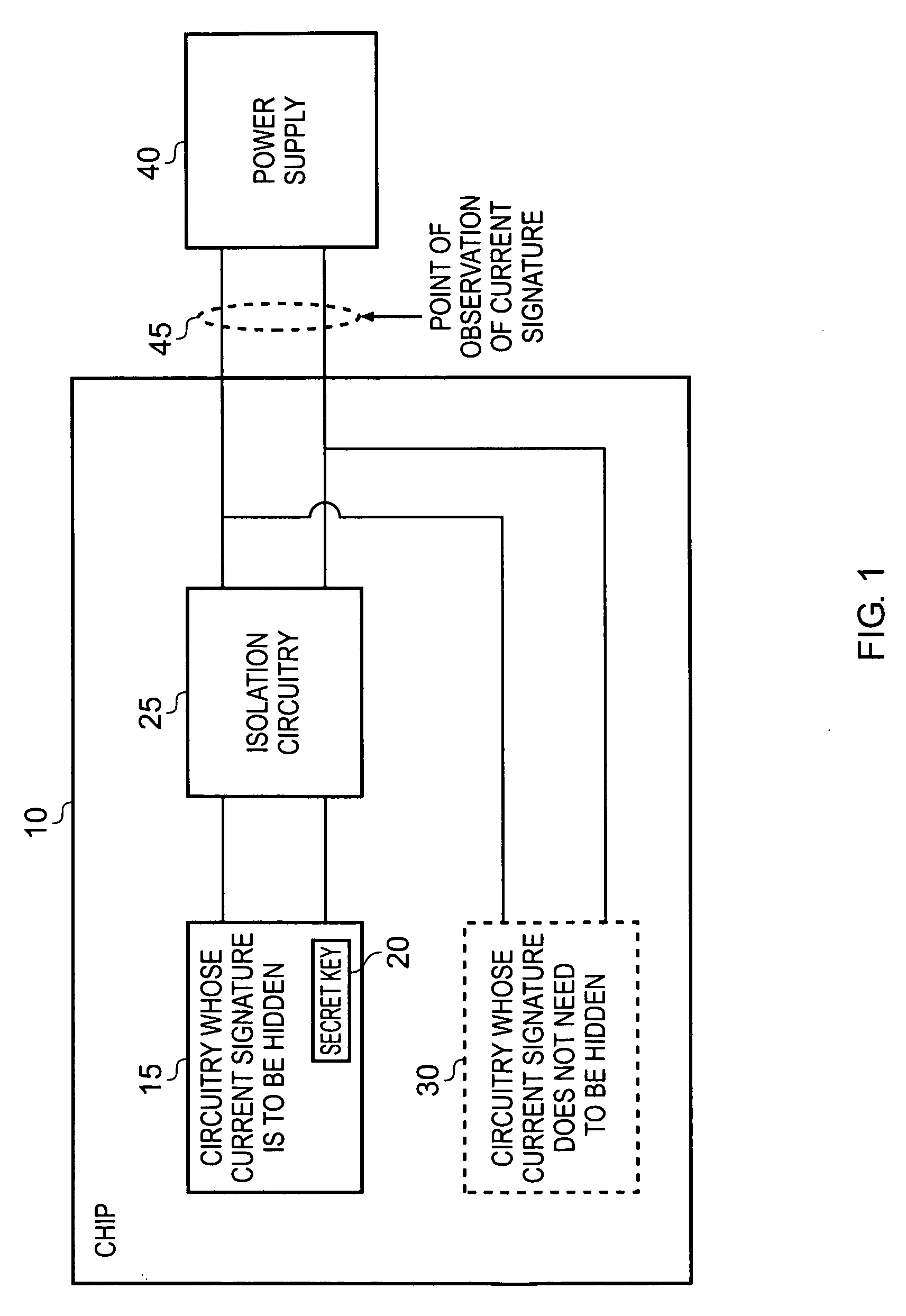
[0047]FIG. 1 is block diagram illustrating an integrated circuit in accordance with an embodiment of the present invention. In this example, the integrated circuit takes the form of a chip 10, which in one particular embodiment may be a smart card. The chip 10 includes circuitry 15 whose current signature is to be hidden, such that it can not be observed at an observation point 45 between a chip 10 and the power supply 40. In particular, the circuitry 15 performs data processing operations using some secret data which an attacker may seek to determine using DPA techniques, these techniques typically involving the placing of analysis circuitry including resistive elements between the power supply lines at the location 45 in order to obtain current signature information dependent on the power drawn by the chip 10 from the power supply.

[0048]The analysis circuitry uses a model of the circuitry 15, that model having been derived from available information about the operations being perf...


PUM


Abstract

An isolation circuitry and method are provided for coupling between a power supply and processing circuitry in order to provide power to the processing circuitry whilst hiding a power consumption characteristic of that processing circuitry. The isolation circuitry comprises a plurality of sub-circuits, with each sub-circuit comprising a capacitor, a first switch configured to provide a first connection between the capacitor and the power supply, a second switch configured to provide a second connection between the capacitor and the processing circuitry, and a third switch configured to provide a third connection across the capacitor to partially discharge the capacitor. Control circuitry controls the plurality of sub-circuits, such that within each sub-circuit the first switch, second switch and third switch are placed in an active state in a repeating sequence. Each of the plurality of sub-circuits further comprises a comparator configured to place the third switch in an open state when a predetermined non-zero voltage difference across the capacitor is reached during the active state of the third switch. By such an approach, it is ensured that the voltage across the comparator at the end of the discharge operation is always the same irrespective of the voltage present at the start of the discharge operation. As a result, the power consumption characteristic of the processing circuitry is entirely hidden by the isolation circuitry. Further, the isolation circuitry of the present invention provides a particular power efficient mechanism for hiding the power consumption characteristic of the processing circuitry.

Description

BACKGROUND OF THE INVENTION[0001]1. Field of the Invention[0002]The present invention relates to an isolation circuitry and method for coupling between a power supply and processing circuitry in order to provide power to the processing circuitry whilst hiding a power consumption characteristic of that processing circuitry.[0003]2. Description of the Prior Art[0004]It is known to provide processing circuits which perform data processing operations using secret data which needs to be protected against unauthorised access. For example, it is known to provide processing circuits that perform encryption and decryption using particular encryption and decryption algorithms that make use of secret data such as a secret key. As a particular example, the algorithms specified by the Advanced Encryption Standard (AES) make use of a secret key to perform encryption and decryption operations. Unencrypted input data (referred to as plaintext) may be encrypted using the secret key to produce encryp...

Claims


Application Information

Patent Timeline
Patent Type & Authority Applications(United States)
IPC IPC(8): G05F3/02
CPCG06F21/556G06F1/26G06F21/77H02M3/07
Inventor TOKUNAGA, CARLOS ALFONSOBLAAUW, DAVID THEODORE
Owner RGT UNIV OF MICHIGAN
Why Eureka
Try Eureka