Charging monitor

a monitor and charging technology, applied in the direction of safe/protective circuits, light to electrical conversion, electric devices, etc., can solve the problems of earth-leakage monitor malfunction, discomfort, and electric leakage at the time of charging, and achieve accurate detection and further false detection

Active Publication Date: 2010-08-05
PANASONIC CORP
View PDF13 Cites 101 Cited by
  • Summary
  • Abstract
  • Description
  • Claims
  • Application Information

AI Technical Summary

Benefits of technology

[0008]According to this configuration, the charging monitor is interposed between the load section having a storage battery and the external AC power supply when charging is performed. When the electric leakage determination circuit determines at the time of charging that an electric leakage has occurred, the switch disconnects the load section from the external AC power supply, whereby a charging operation is stopped. The current detection circuit outputs a detection signal of a voltage corresponding to the difference in level between the currents flowing through the lines of the external AC power supply. This detection signal is output as a signal having the same phase as an AC current flowing through each line. The suppression circuit suppresses the DC component contained in the detection signal. Furthermore, the filter circuit filters the plurality of frequency components contained in the detection signal so that attenuation increases as a frequency becomes high. In other words, the filter circuit performs filtering so that the plurality

Problems solved by technology

In this case, an electric leakage might occur at the time of charging, due to a poor connection between the charging line and the device or an insulation defect caused around the battery of the device.
Moreover, in a structure where the device is insulated from the ground, an electric charge caused by electric leakage at the time of charging flows to the ground through a human body, causing a discomfort feeling.
However, in Patent Document 1, the detecting circuit is not for detecting a minute earth

Method used


Image

  • Charging monitor
  • Charging monitor
  • Charging monitor

Examples


Embodiment Construction

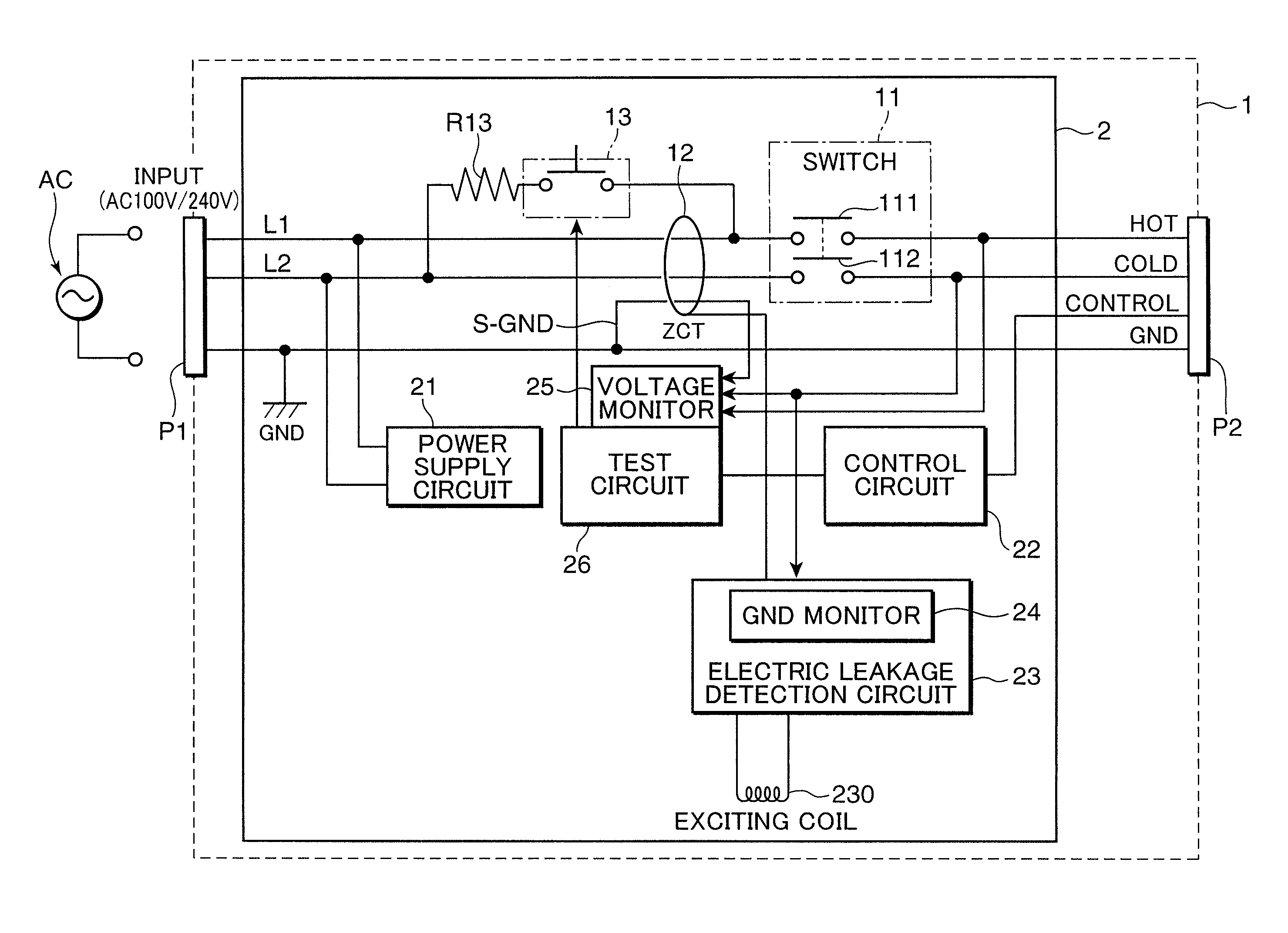
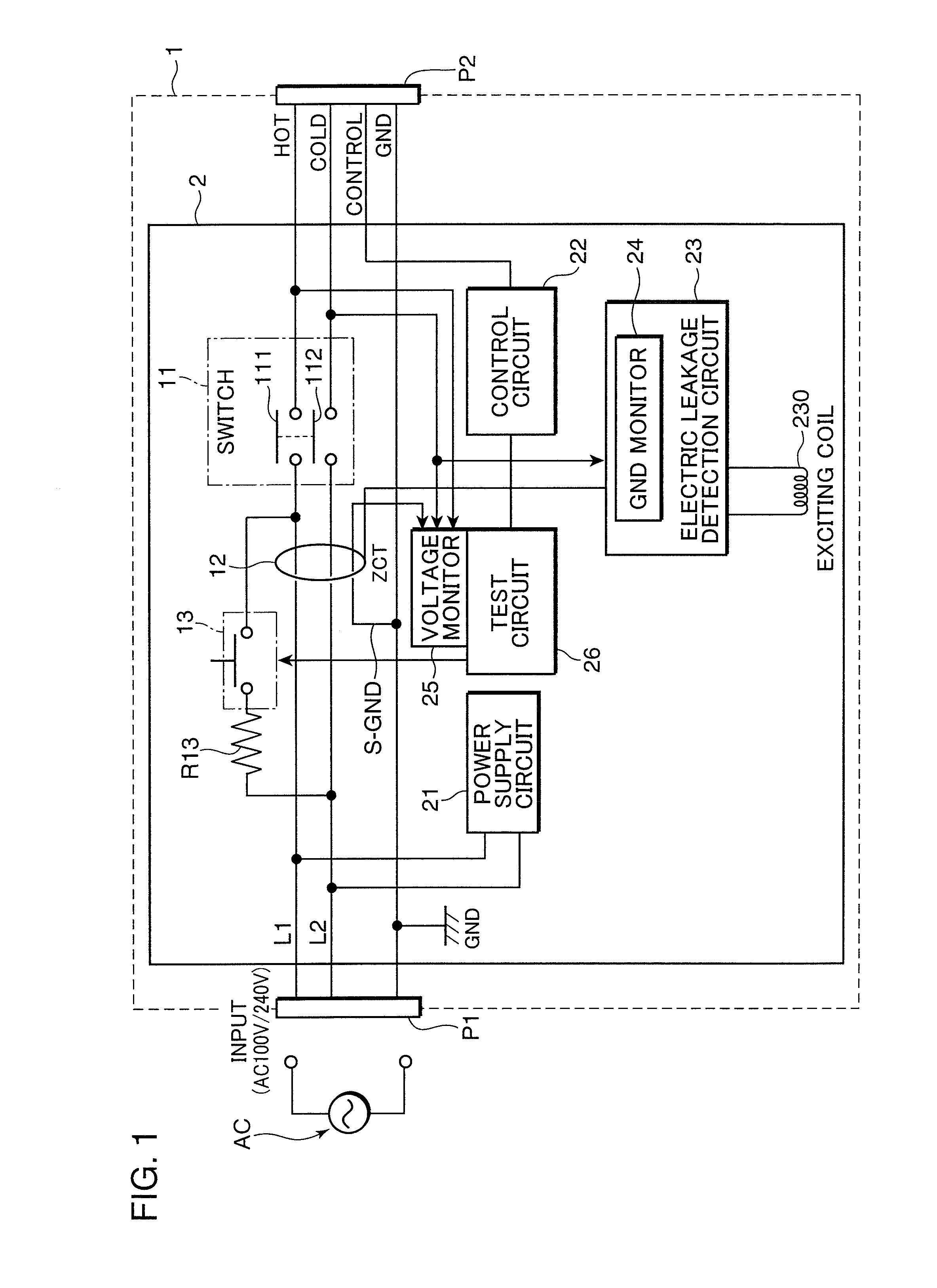
[0016]FIG. 1 is a block diagram showing an embodiment of the case where a charging monitor of the present invention is applied to a charging device having a storage battery (battery). In FIG. 1, a charging monitor 1 has a plug P1 connected to an external AC power supply AC, a plug (socket) P2 connected to the battery of the charging device (load section), and a circuit block 2 for monitoring the charging of the battery, between the plug P1 and the plug P2. AC lines L1, L2 (Hot, Cold), a ground line (GND), and a control signal line between the charging monitor 1 and the load section are provided between the plugs P1, P2.

[0017]A circuit block 2 for monitoring the charging of the battery has a switch 11 serving as an electromagnetic relay (breaker) interposed between the AC lines L1, L2, a residual current transformer (ZCT) 12 serving as a current detection circuit provided between the AC lines L1, L2 on the external AC power supply AC side, and an electromagnetic relay 13 used for tes...


PUM


Abstract

A charging monitor has: a switch that is disposed between a load section having a storage battery and an external AC power supply supplying a current to the load section via a plurality of lines and interrupts the supply of the current from the external AC power supply to the load section; a current detection circuit that outputs a detection signal corresponding to a difference in level between currents flowing through the lines; a suppression circuit that suppresses a DC component contained in the detection signal; a filter circuit that filters a plurality of frequency components contained in the detection signal so that attenuation increases as a frequency becomes high; a rectifier smoothing circuit that rectifies and smoothens an output signal obtained when the detection signal passes through the filter circuit and the suppression circuit; and an electric leakage determination circuit that detects an electric leakage and shuts off the switch when the level of the signal smoothened by the rectifier smoothing circuit exceeds a preset reference level.

Description

TECHNICAL FIELD[0001]The present invention relates to a charging monitor, which is interposed between a load section having a storage battery and an external AC power supply and has an electric leakage determination circuit and a switch for disconnecting the load section from the external AC power supply when the electric leakage determination circuit determines that electric leakage has occurred.BACKGROUND ART[0002]There has conventionally been known an auxiliary power supply system that is capable of, if needed, pulling out electric power accumulated in a battery or an electric vehicle driven by electric power of a battery. A battery provided to such device is charged mainly by a household or industrial external AC power supply. In this case, an electric leakage might occur at the time of charging, due to a poor connection between the charging line and the device or an insulation defect caused around the battery of the device. It is desired that such electric leakage is detected i...

Claims


Application Information

Patent Timeline
IPC IPC(8): H02J7/10B60L50/16
CPCH01H83/144Y02T90/127H02J7/0031B60L3/003B60L8/003B60L8/006B60L11/14B60L11/1824B60L2210/30B60L2240/529B60L2240/527B60L3/0069B60L3/04B60L11/1816Y02T10/7077Y02T10/7005Y02T10/7241Y02T10/70Y02T10/7083Y02T90/121Y02T90/14H02H3/33Y02T10/7072B60L53/14B60L50/16Y02T10/72Y02T90/12
Inventor GOTOU, KIYOSHIKOSHIN, HIROAKIOOYA, HIROSHI
Owner PANASONIC CORP
Why Eureka
Try Eureka