Amorphous metal continuous flux path transformer and method of manufacture

a technology of transformers and flux paths, applied in transformers/inductances, magnets, magnetic bodies, etc., can solve the problems of energy loss, energy loss, and estimated 10% of all electricity generated, and achieve the effects of enhancing varnish penetration, promoting varnish flow, and reducing energy loss

Inactive Publication Date: 2010-08-05
HEXAFORMER AB
View PDF21 Cites 34 Cited by
  • Summary
  • Abstract
  • Description
  • Claims
  • Application Information

AI Technical Summary

Benefits of technology

[0029]Further, according to the invention there is provided a method of making a three phase transformer with an amorphous metal core or hybrid core comprising forming an amorphous metal transformer core with three legs, and winding at least one transformer winding onto the core using a winding tube, thereby avoiding having to cut the core in order to receive the winding.
[0030]Still further, according to the invention, there is provided a method of making an amorphous metal transformer core with a continuous flux path configuration, e.g., hexaformer configuration, wherein the core is made of three frames, each made of at least three rings, at least one of the rings being composed at least partially of multiple layers of amorphous metal, comprising securing the multiple layers of amorphous metal relative to each other to avoid them slipping relative to each other. Typically the amorphous metal layers are wound onto a winding head from an amorphous metal reel. The securing of the amorphous metal l...

Problems solved by technology

As mentioned above, one important issue in transformer design is energy loss, and in the energy distribution industry the opportunities for energy loss are numerous.
An estimated 10% of all electricity generated is lost because of distribution inefficiency.
The cutting of the core however causes numerous breaks in the continuity of the core material, which leads to interference in the magnetic flux path and core losses.
The cutting and rejoining process again creates breaks in the core layers that significantly increase the core losses
It will be appreciated that although this core construction makes use of layers having a wound configuration that avoids sharp corners with the breaks in the core layers, it nevertheless typically involves hundreds and even thousands of breaks in the amorphous metal strip causing numerous interruptions in the flux path, which leads to losses in the core.
As mentioned above, the use of a bobbin is, however, very limited by design constraints since it requires enough window space between the core legs to allow the bobbin to pass through the window even when the other legs are already wound w...

Method used


Image

  • Amorphous metal continuous flux path transformer and method of manufacture
  • Amorphous metal continuous flux path transformer and method of manufacture
  • Amorphous metal continuous flux path transformer and method of manufacture

Examples


Embodiment Construction

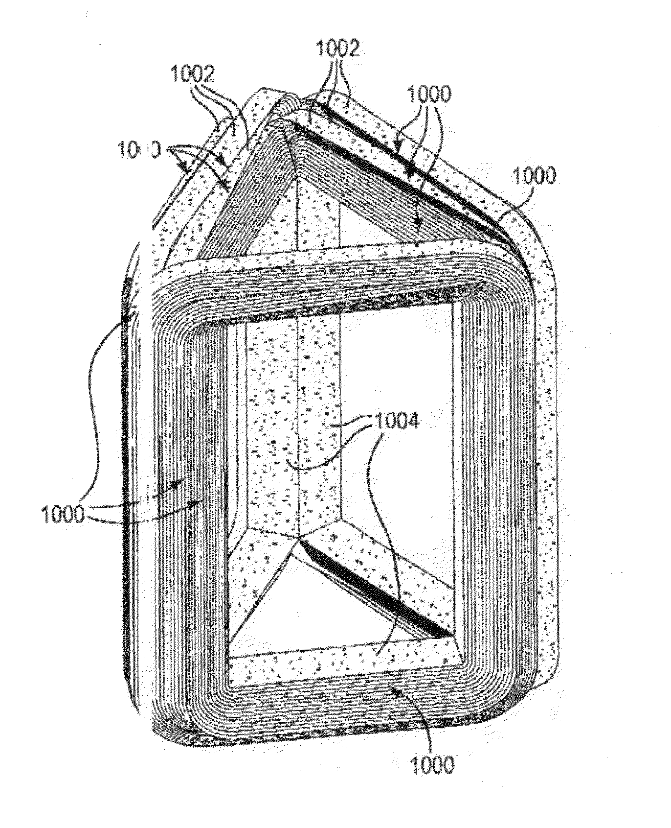
[0051]The present invention includes the production of any continuous flux path amorphous metal three phase transformers. As defined above for purposes of this application, a continuous flux path core comprises a core that does not involve breaks in the core layers or require cutting of the core layers, in order to place (land) the cores on the leg of the core. This therefore requires winding the transformer coils onto the core legs. As discussed above, this can be achieved either by the use of a bobbin passed through the window of the transformer core or by using a winding tube. The use of a bobbin is very limited by design constraints since it requires enough window space to allow the bobbin to pass through the window even when the other legs are already wound with coils and thus have the effect of reducing the window size.

[0052]The alternative, and the one that will be adopted by the present invention is the use of winding tubes that are attached around the legs in a rotatable fa...


PUM

PropertyMeasurementUnit
Widthaaaaaaaaaa
Efficiencyaaaaaaaaaa
Stiffnessaaaaaaaaaa

Abstract

In a three phase transformer core, amorphous metal strips are wound into rings that are combined into frames and assembled to define cores with leg cross sections that have more than 4 sides to facilitate winding transformer windings onto the legs using winding tubes. The amorphous metal layers are secured relative to one another and the core made more rigid using resin, silicon steel layers included in the amorphous metal core, or by using strapping or tying devices.

Description

[0001]This application is a non-provisional application that claims priority from U.S. provisional patent applications 61 / 206,907 filed Feb. 5, 2009 to John Hurst and 61 / 212,660 filed Apr. 14, 2009 to John Hurst et al.FIELD OF THE INVENTION[0002]The invention relates to transformers. In particular it relates to transformers made of an amorphous metal.BACKGROUND OF THE INVENTION[0003]Transformers operate on the principle that when two wires are arranged in proximity to each other and an alternating current is passed through one of the wires, an alternating current is induced in the other wire by an effect known as electromagnetic induction. By winding the wires into coils and placing the coils along a common axis the amount of electromagnetic coupling and thus the amount of induced current will be increased over straight, parallel wires. The coupling is increased yet further by winding the two coils on top of each other. The coupling can also be increased by placing a ferromagnetic s...

Claims


Application Information

Patent Timeline
IPC IPC(8): H01F27/24H01F41/06
CPCH01F27/23H01F27/263H01F41/005H01F41/0226Y10T29/49071H01F3/02H01F41/06Y10T29/49073H01F2003/106
Inventor HURST, JOHN SHIRLEYVOLLRATH, JURGEN KLAUS
Owner HEXAFORMER AB
Why Eureka
Try Eureka