Display device

a display device and display screen technology, applied in the field of display screens, can solve the problems of terminals peeling at a later time, defective connections, etc., and achieve the effects of avoiding an increase in the number of pins of the fpc board, minimizing production costs, and simplifying the configuration for conversion

Inactive Publication Date: 2010-08-05
SHARP KK
View PDF7 Cites 19 Cited by
  • Summary
  • Abstract
  • Description
  • Claims
  • Application Information

AI Technical Summary

Benefits of technology

[0042]According to the first aspect of the present invention, the signal externally provided to the second unit is optically transmitted from the optical transmitter to the optical receiver of the first unit having provided therein the pixel formation portions and the predetermined circuitry, and therefore it is possible to omit a transmission medium (typically, the FPC board) for externally providing the signal to the first unit, or it is possible to avoid an increase in the number of pins of the FPC board, regardless of an increase in functions.
[0043]According to the second aspect of the present invention, because the signal to be transmitted is transmitted using the backlight source that emits illumination light, it is not necessary to provide an additional light emitting device for optical transmission, and the drive circuit for backlighting can also be used for generating light signals, making it possible to minimize production cost.
[0044]According to the third aspect of the present invention, the backlight source is driven by the signal subjected to conversion for baseband transmission, and therefore it is possible to simplify the configuration for conversion. In addition, when transmitting digital signals consisting of a pulse string, almost no flickering can occur. Furthermore, when the backlight source is under dimming control by a pulse according to PWM or suchlike, the pulse can be used for baseband transmission, resulting in efficient optical transmission.
[0045]According to the fourth aspect of the present invention, because the backlight source is driven by the signal subjected to modulation for band transmission, it is possible to facilitate separation of the modulated signal in the optical receiver, making it possible to reduce transmission errors.
[0046]According to the fifth aspect of the present invention, because the backlight source is a sheet illuminator, such as an EL backlight, it is possible to obtain uniform illumination light with a simplified configuration, freely set the position of the optical receiver, and eliminate the necessity to form optical paths for the light, e.g., the necessity to provide through-holes.
[0047]According to the sixth aspect of the present invention, because the optical receiver receives the illumination light passing through the light guide, it is possible to freely set the position of the optical receiver compared to the configuration in which the light is directly received from the optical transmitter, and it is also possible to eliminate the necessity to form optical paths for the light, e.g., the necessity to provide through-holes.

Problems solved by technology

As such, because the FPC board having a large number of pins is crimped to input terminals on the glass substrate, defective connections can readily occur, and even if the connections are satisfactorily completed, the terminals might peel at a later time due to vibrations or repairs after mounting to mobile equipment.

Method used


Image

  • Display device
  • Display device
  • Display device

Examples


first embodiment

1. First Embodiment

1.1 overall Configuration and Operation

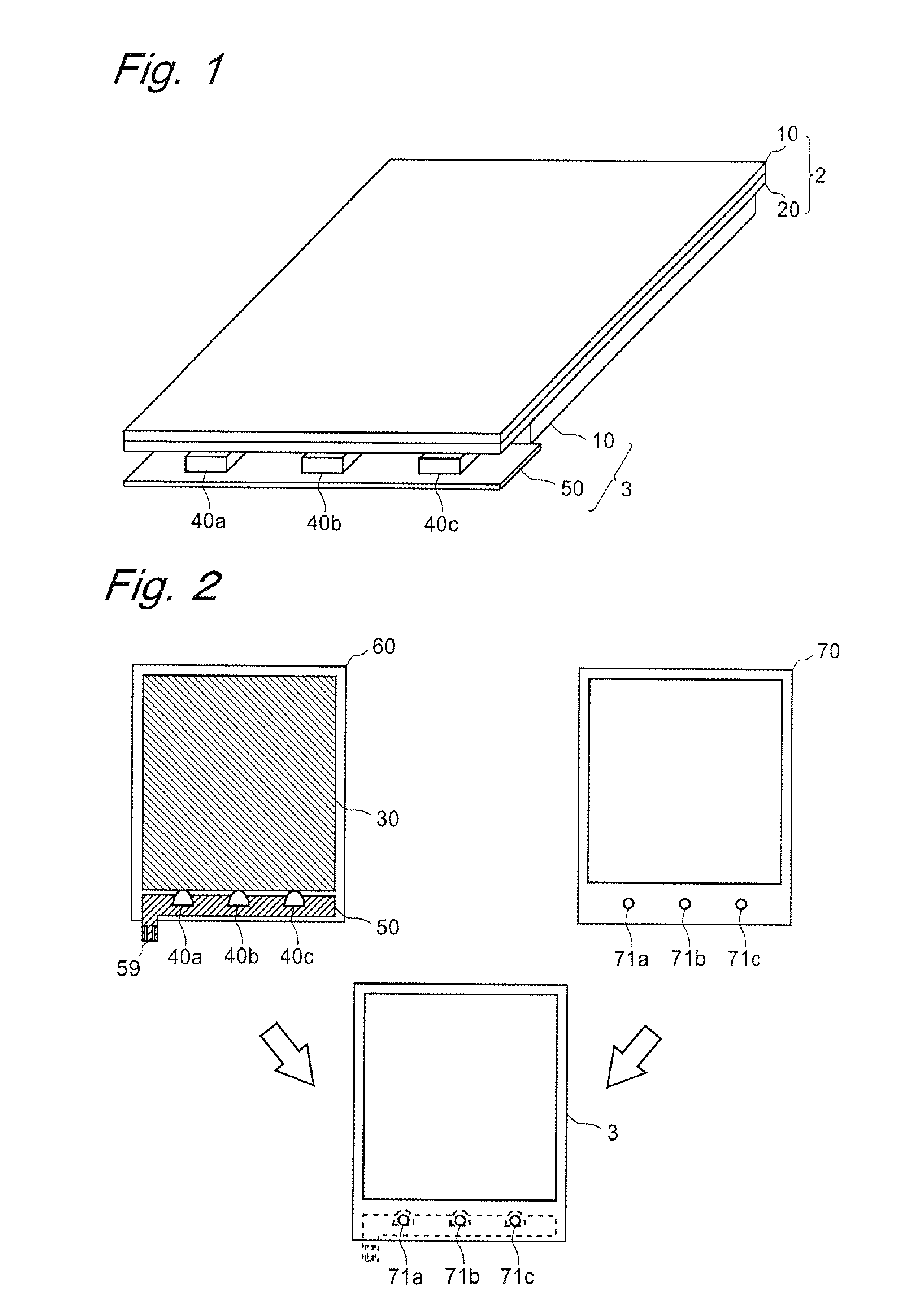
[0142]FIG. 1 is a perspective view for describing a partial structure of a liquid crystal display device according to the first embodiment of the present invention. This liquid crystal display device is a transmissive (or semi-transmissive) liquid crystal display device configured almost in the same manner as conventionally but differing from the conventional configuration in that light detectors and a receiver circuit for signal transmission to be described later are additionally included, in place of the FPC board for video signal transmission.

[0143]As shown in FIG. 1, the liquid crystal display device includes: a liquid crystal display panel (liquid crystal display unit) 2, which includes a CF substrate 10 similar to the conventional one and a TFT substrate 20 differing from the conventional one and having formed thereon light detectors and a receiver circuit; and a backlight portion (backlight unit) 3, which includes whit...

second embodiment

2. Second Embodiment

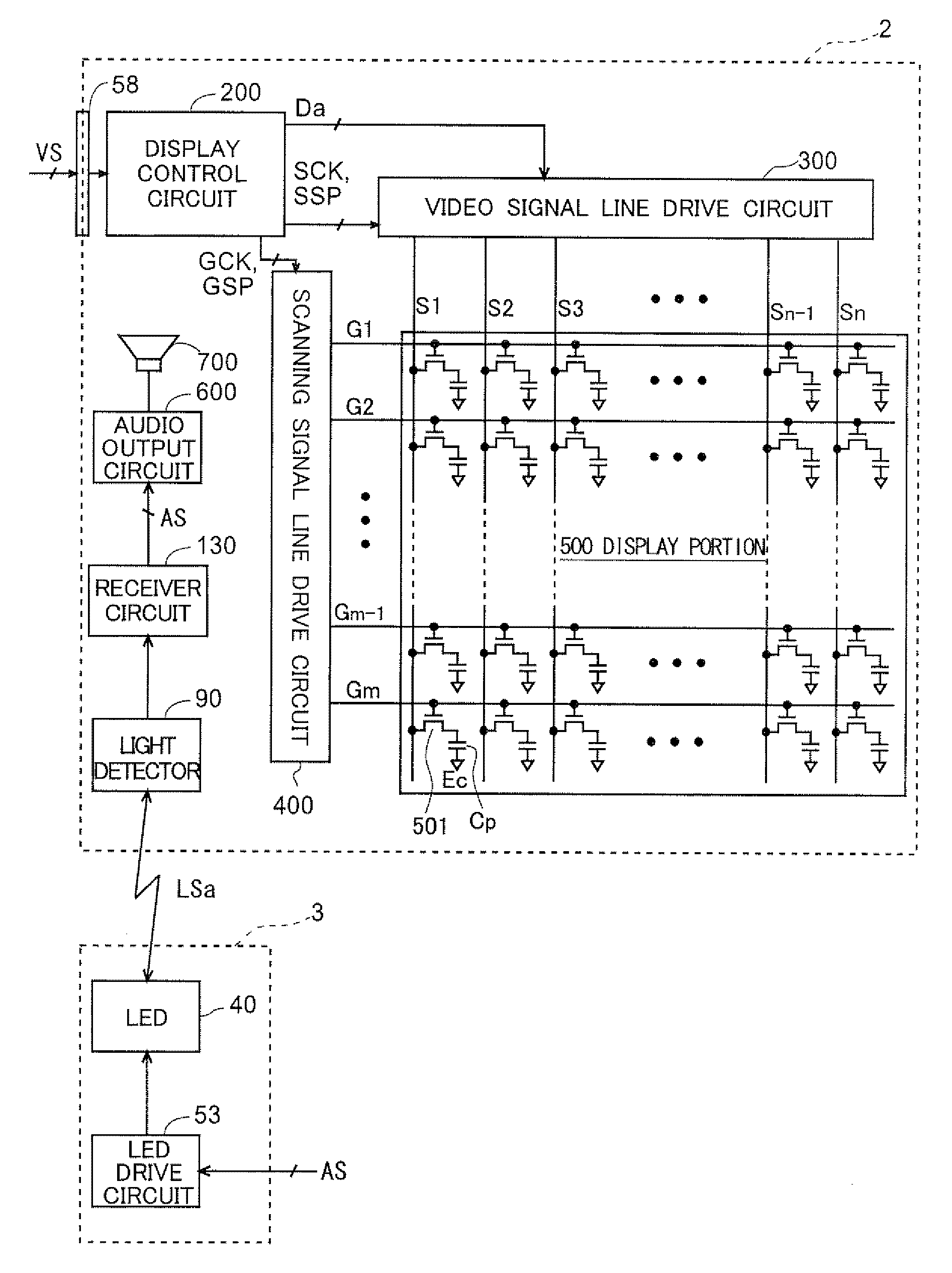
[0184]Next, in the present embodiment, unlike in the first embodiment, so-called dimming control is operated, in which when the white LEDs 40a to 40c are operating, i.e., when backlighting is performed, the white LEDs 40a to 40c repeat lighting and extinguishing at extremely short time intervals, for example, with an invisible frequency of about 100 [KHz]. The dimming control is performed by changing the duty ratio indicating the ratio of lighting time and extinguishing time, and for example, the overall brightness of the white LEDs 40a to 40c decreases as the proportion of the extinguishing time increases. Accordingly, for example, it is possible to provide backlighting with desired brightness suitable for the brightness of the outside light, and it is also possible to reduce power consumption compared to the case where the white LEDs 40a to 40c are always lit. The circuit configuration of the liquid crystal display device for performing such dimming control is ...

third embodiment

3. Third Embodiment

[0200]Next, unlike in the first and second embodiments, the liquid crystal display device in the present embodiment has the function of reproducing audio, in addition to the main function of displaying video. Specifically, in the present embodiment, the video signal VS is transmitted by the FPC board for video signal transmission, which is configured as conventionally, and only an additionally-provided audio signal AS is transmitted by a light signal. The circuit configuration of the liquid crystal display device in such a case will be described.

[0201]Here, because the structure of the liquid crystal display device in the present embodiment is similar to that in the first embodiment, the same elements are denoted by the same characters, and any descriptions thereof will be omitted. In addition, because the overall circuit configuration of the present liquid crystal display device is also analogous to that in the first embodiment, the same elements are denoted by t...


PUM


Abstract

A display device is provided, including a signal transmission mechanism that makes it possible to reduce the number of pins on an FPC board connected to a TFT substrate or eliminate the necessity for the FPC board, and that can be readily applied to a compact device.
The present liquid crystal display device includes light detectors, a receiver circuit, a display control circuit, a video signal line drive circuit, a scanning signal line drive circuit, and a display portion, which are formed on a TFT substrate of a liquid crystal display panel, and it also includes white LEDs, and an LED drive circuit, which are included in a backlight portion. The LED drive circuit drives the white LEDs, each emitting a light (modulation) signal LS in accordance with an externally-provided video signal VS. The receiver circuit generates (demodulates) the video signal VS based on a signal received via the light detector. Such an optical transmission mechanism makes it possible to reduce the number of pins on the FPC board or eliminate the FPC board.

Description

TECHNICAL FIELD[0001]The present invention relates to display devices, and more specifically to a display device employing an optical communication scheme therein.BACKGROUND ART[0002]Conventionally, active-matrix liquid crystal display devices provided with TFTs (thin film transistors) as switching elements are known well as general display devices. Such a liquid crystal display device includes a liquid crystal display panel composed of two opposing insulating substrates (typically, glass substrates). One substrate of the liquid crystal display panel (hereinafter, referred to as a “TFT substrate”) has scanning signal lines (gate bus lines) and video signal lines (source bus line) provided in the form of a lattice, and the TFT is provided in the vicinity of each intersection between the scanning signal line and the video signal line. The TFT has a gate electrode connected to the scanning signal line, a source electrode connected to the video signal line, and a drain electrode. The dr...

Claims


Application Information

Patent Timeline
Patent Type & Authority Applications(United States)
IPC IPC(8): G09G5/10
CPCG02F1/13452G02F2001/133612G06F3/14G09G3/2096G09G2370/08G09G2320/0626G09G2360/145G09G2370/04G09G3/3406G02F1/133612G09G3/36G09G3/20G02F1/133G02F1/1335
Inventor MIYATA, KAZUHIKOBROWNLOW, MICHAEL JAMESWALTON, HARRY GARTH
Owner SHARP KK
Why Eureka
Try Eureka