Supercharge Your Innovation With Domain-Expert AI Agents!

Characterization of optical systems

a technology of optical systems and power maps, applied in the field of optical systems, can solve the problems of inability to apply techniques to eyes in vivo, inability to generate useful power maps of contact lenses, and limited number of rays that can be employed

Inactive Publication Date: 2010-08-05
INST FOR EYE RES
View PDF28 Cites 8 Cited by
  • Summary
  • Abstract
  • Description
  • Claims
  • Application Information

AI Technical Summary

Benefits of technology

[0014]From one aspect, this invention involves directing an incident beam onto spots on an optical surface so as to generate an emergent beam for each spot, determining the lateral location of each emergent beam at first and second optical distances from the surface and deriving the optical power at each spot therefrom. Normally this will involve calculating the emergent angle of the emergent beam at each spot. The resulting data can then be used to determine the optical characteristics of the system. Normally, the scanning of the incident beam, the computation of emergent beam angles, the generation of the data-set and its visual presentation will be computer-controlled or mediated. This will allow a wide variety of optical characteristics of the optical system to be generated and, if desired, to be visually mapped onto a representation of the optical surface.
[0019]While the detector arrays are preferably of the planar two-dimensional ‘area’ type so that each can immediately output the lateral coordinates of the emergent beam at its location, narrow linear detector arrays can also be employed if intersections along specific meridians only are of interest. Otherwise, such linear detector arrays can be rotated or crossed at a location to effectively act as full or partial area arrays.
[0022]The use of more than two detectors at different distances can enhance the precision with—or the range over—which the coordinates of the emergent beam can be determined at a given plane or location. The additional detector or detectors can be positioned intercept emergent beams that are deflected more or less normal. For example, when a more powerful lens than normal is being mapped, the emergent beam may be ‘super-deflected’ to such a degree that it misses the more remote of two ‘standard’ detectors. A third detector could thus be positioned to intercept the super-deflected emergent beam. An additional beam-divider may be used to deflect portion of the emergent beam to the additional detector. Alternatively, (as indicated above) the ‘standard’ remote detector could be moved to intercept the super-deflected beam. Conversely, if a weaker lens than normal is being characterized, the ‘standard’ near detector may be positioned too close to read the emergent beam coordinates with sufficient accuracy and the near detector might be moved further away or a third, more remote detector, with an associated beam-divider may be used for that purpose. Many other arrangements are possible within the scope of the present invention.

Problems solved by technology

It should also be noted that ray-tracing methods assume that the position of a lens surface along the optical axis of the instrument is known with precision, which is problematic in the case of optical devices with small, strongly curved or figured surfaces, or which are flexible like soft contact lenses.
The number of rays that can be employed is strictly limited by the need to visualize and distinguish them in side view.
The accuracy and resolution of such a map would leave a lot to be desired and the crudeness and laboriousness of the technique makes it quite impractical as a method for generating useful power maps of contact lenses for production quality control.
The technique cannot, of course, be applied to eyes in vivo.

Method used


Image

  • Characterization of optical systems
  • Characterization of optical systems
  • Characterization of optical systems

Examples


Embodiment Construction

[0032]Having portrayed the nature of the present invention, particular examples will now be described with reference to the accompanying drawings. However, those skilled in the art will appreciate that many variations and modifications can be made to the examples provided without departing from the scope of the invention as outlined above and as claimed below. Also, many other examples are possible within the scope of the invention.

DESCRIPTION OF THE SEVERAL VIEWS OF THE DRAWINGS

[0033]In the accompanying drawings:

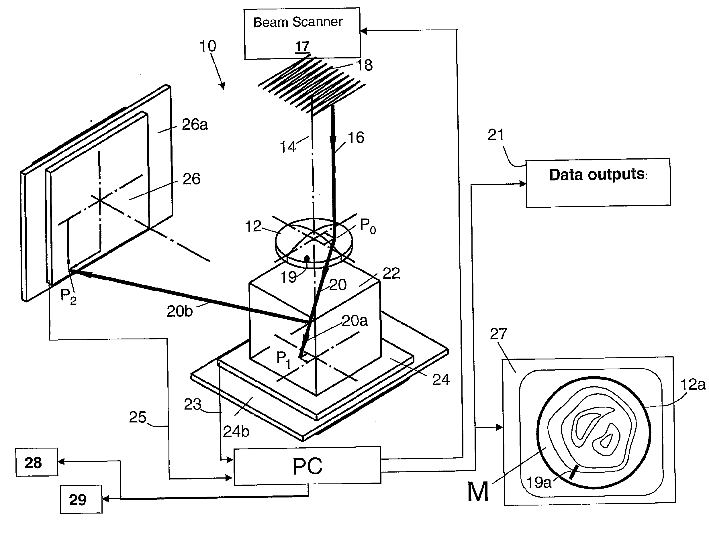
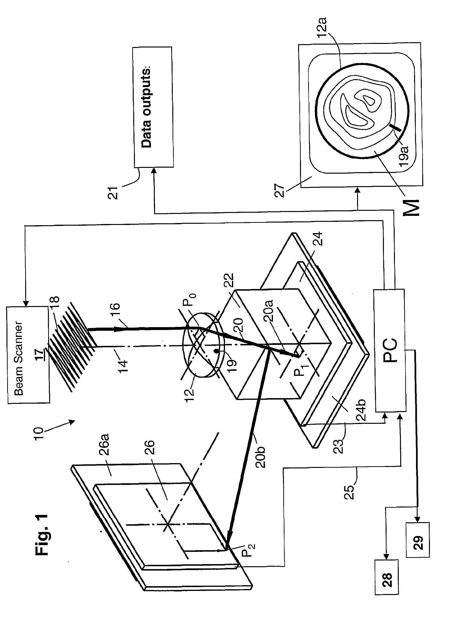
[0034]FIG. 1 is a diagrammatic perspective of the optical layout of an instrument or system that forms the first example of the invention in which the optical system being characterized is a lens, the incident beam is parallel to the optical axis of the lens and raster-scanned over the surface of the lens and in which a fixed beam-divider is employed.

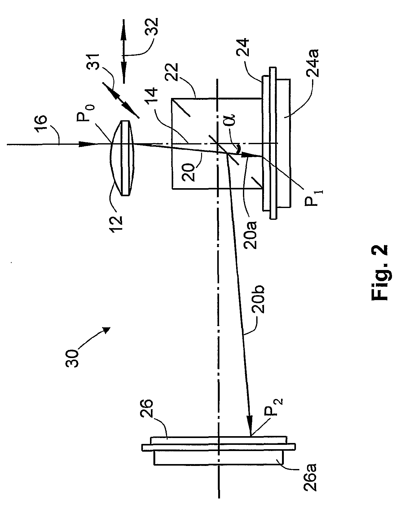
[0035]FIG. 2 is a diagrammatic side elevation of a portion of the instrument of FIG. 1 and comprises a first variant of the i...


PUM


Abstract

An instrument and method is for characterizing the optical properties of an optical system, such as a lens, another optical device or the human eye, over an optical surface of the optical system. In one example, an incident beam is scanned over the surface of a lens to generate an emergent beam that is divided by a beam-splitter into two portions that are directed to respective two-dimensional detector arrays located at different optical distances from the lens. The detector arrays output the lateral coordinates of the points of incidence of the respective emergent beam portions so that the angle of emergent beam with respect to the optical axis or incident beam can be accurately determined. Determining the variation in the angle of the emergent beam over the surface of the lens allows many important optical characteristics of the lens to be characterized and mapped onto to the surface of the lens.

Description

BACKGROUND OF THE INVENTION[0001]1. Technical Field[0002]This invention broadly relates to methods, instruments and apparatus for use in the characterization of optical systems, devices and elements. It is applicable to the determination of reflective and refractive characteristics of figured optical elements such as lenses, mirrors and even complex optical systems such as natural or model eyes and optical instruments.[0003]One use of such methods and apparatus is mapping or spatially resolving refractive power over the area of a lens, which is sometimes referred to as the determination of wave-front aberrations of the lens. The instruments or apparatus concerned include wave-front sensors that can be used with the human eye, with isolated lenses, sets of lenses, mirrors and figured reflective or refractive surfaces (collectively referred to herein as ‘optical system(s)’). Of particular practical interest is mapping the refractive power of ophthalmic lenses, and more specifically of...

Claims


Application Information

Patent Timeline
Patent Type & Authority Applications(United States)
IPC IPC(8): G01M11/02A61B3/10
CPCA61B3/103G01M11/0257G01M11/0235A61B3/107G01M11/02G02B27/00
Inventor HO, ARTHUREHRMANN, KLAUS
Owner INST FOR EYE RES
Features
  • R&D
  • Intellectual Property
  • Life Sciences
  • Materials
  • Tech Scout
  • Unparalleled Data Quality
  • Higher Quality Content
  • 60% Fewer Hallucinations
Learn More