Image decoding apparatus, image decoding method, image coding apparatus, and image coding method

a technology of image coding and decoding apparatus, applied in the direction of electrical apparatus, instruments, computing, etc., can solve the problems of inability to obtain information on adjacent macroblocks mb, parallel processing cannot be achieved, etc., and achieve the effect of reducing cost, efficient operation and high performan

Inactive Publication Date: 2010-08-05
SOVEREIGN PEAK VENTURES LLC
View PDF37 Cites 26 Cited by
  • Summary
  • Abstract
  • Description
  • Claims
  • Application Information

AI Technical Summary

Benefits of technology

[0017]The image decoding apparatus and the image coding apparatus according to the present invention can achieve higher performance and lower cost by efficiently operating a plurality of decoding units or a plurality of coding units in parallel while solving dependencies on neighboring macroblock information with a small amount of information transferred, in a coding system that exploits correlation with neighboring macroblocks to enhance compression efficiency.
[0019]The disclosure of Japanese Patent Application No. 2008-135133 filed on May 23, 2008 including specification, drawings, and claims is incorporated herein by reference in its entirety.

Problems solved by technology

However, in the case of processing each row (macroblock line) of the picture Pic in parallel, simply processing macroblocks MB positioned in the same column of the different rows in parallel makes it impossible to obtain information on adjacent macroblocks MB necessary for each processing target macroblock MB, so that such parallel processing cannot be achieved.

Method used


Image

  • Image decoding apparatus, image decoding method, image coding apparatus, and image coding method
  • Image decoding apparatus, image decoding method, image coding apparatus, and image coding method
  • Image decoding apparatus, image decoding method, image coding apparatus, and image coding method

Examples


first embodiment

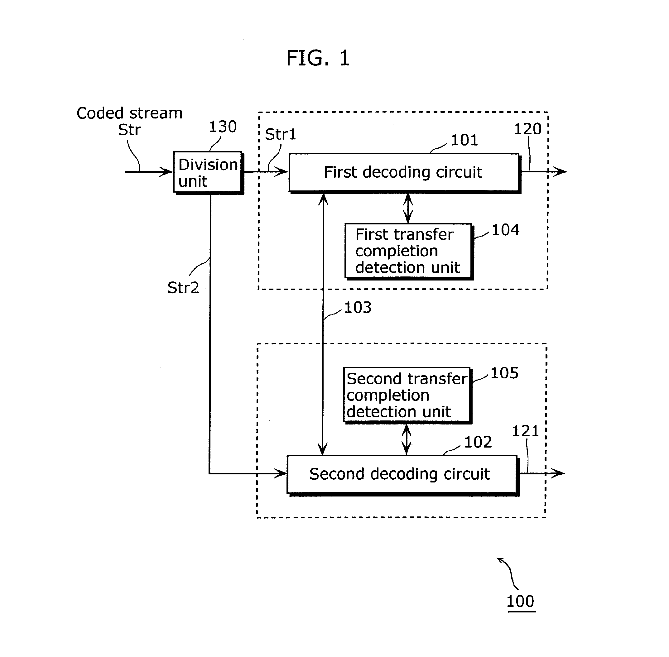
[0044]FIG. 1 is a block diagram showing a structure of an image decoding apparatus in a first embodiment of the present invention.

[0045]An image decoding apparatus 100 in this embodiment includes: a division unit 130 that divides a coded stream Str obtained by coding data showing a moving image according to H.264, and outputs divided coded streams Str1 and Str2; a first decoding circuit 101 that decodes the divided coded stream Str1; a second decoding circuit 102 that decodes the other divided coded stream Str2 in parallel with the decoding process by the first decoding circuit 101; an information transfer bus (data bus) 103 for transferring information between the first decoding circuit 101 and the second decoding circuit 102; and a first transfer completion detection unit 104 and a second transfer completion detection unit 105 that detect completion of information transfer performed between the first decoding circuit 101 and the second decoding circuit 102.

[0046]Note that the firs...

second embodiment

[0133]An image coding apparatus in this embodiment is an apparatus that codes a picture per macroblock according to H.264, and has the same features as the image coding apparatus in the first embodiment. The only difference between the image coding apparatus in this embodiment and the image coding apparatus in the first embodiment is whether macroblocks are coded or decoded. The following describes the image coding apparatus in this embodiment in detail, with reference to FIGS. 12 to 16.

[0134]FIG. 12 is a block diagram showing a structure of the image coding apparatus in the second embodiment of the present invention.

[0135]An image coding apparatus 200 in this embodiment includes: a division unit 230 that divides moving image data Pin and outputs divided moving image data Pin1 and Pin2; a first coding circuit 201 that codes the divided moving image data Pin1; a second coding circuit 202 that codes the other divided moving image data Pin2 in parallel with the coding process by the fi...

third embodiment

[0173]This embodiment is an application of the image decoding apparatus in the first embodiment and the image coding apparatus in the second embodiment, namely, an AV processing unit that realizes a H.264 recorder.

[0174]FIG. 17 is a block diagram of the AV processing unit.

[0175]An AV processing unit 300 in this embodiment is an AV processing unit that reproduces digitally compressed audio and images such as a DVD recorder and a hard disk recorder, and is constructed as an integrated circuit such as LSI. This AV processing unit 300 includes an image coding / decoding unit 301 having the functions and structures of the image decoding apparatus and the image coding apparatus in the first and second embodiments described above, an audio coding / decoding unit 302, an image input / output unit 303, an image processing unit 304, an audio input / output unit 305, an audio processing unit 306, a bus 307, an AV control unit 308, a memory input / output unit 309, and a stream input / output unit 311.

[017...


PUM


Abstract

To provide an image decoding apparatus that suppresses overhead of parallel processing to improve parallelization efficiency and reduce circuit costs, while solving neighboring macroblock dependencies. The image decoding apparatus (100) includes first and second decoding circuits (101, 102) having a transfer unit that transfers right neighborhood information or left neighborhood information, and first and second transfer completion detection units (104, 105) that respectively detect whether or not the left neighborhood information or the right neighborhood information has been transferred to the first and second decoding circuits (101, 102). Each of the first and second decoding circuits (101, 102) decodes a decoding target macroblock positioned at an edge of a region, when the transfer of the left neighborhood information or the right neighborhood information is detected. A boundary line between regions is orthogonal to a decoding direction corresponding to an order in which macroblocks adjacent to each other are sequentially decoded.

Description

TECHNICAL FIELD[0001]The present invention relates to an image decoding apparatus and an image coding apparatus that respectively decode and code moving image information, and in particular relates to an image decoding apparatus that performs decoding by parallel processing and an image coding apparatus that performs coding by parallel processing.BACKGROUND ART[0002]An MPEG (Motion Pictures Experts Group) coding system that uses inter-frame differences is often employed as a technique for compression-coding (hereafter simply referred to as “coding”) moving image information. As the MPEG coding system, in addition to conventionally used MPEG-2 (ISO / IEC 13818-2) and MPEG-4 (ISO / IEC 14496-2), new coding systems such as H.264 / MPEG-4 AVC (ISO / IEC 14496-10) (hereafter simply referred to as “H.264”) and VC-1 (SMPTE 421M) are increasingly used in recent years.[0003]In such coding systems, one screen (picture) is divided into blocks each of which is made up of a predetermined number of pixel...

Claims


Application Information

Patent Timeline
Patent Type & Authority Applications(United States)
IPC IPC(8): G06K9/36
CPCH04N19/176H04N19/61H04N19/44H04N19/436H04N19/85H04N19/107H04N19/177H04N19/00278H04N19/00903H04N19/55
Inventor AMANO, HIROSHIIGUCHI, MASAYASU
Owner SOVEREIGN PEAK VENTURES LLC
Why Eureka
Try Eureka