High selectivity, low damage electron-beam delineation etch

Active Publication Date: 2010-08-05
FEI COMPANY
View PDF43 Cites 35 Cited by
  • Summary
  • Abstract
  • Description
  • Claims
  • Application Information

AI Technical Summary

Benefits of technology

[0009]An object of the invention is to provide an improved method o

Problems solved by technology

In some embodiments, the competing reactions barely f

Method used


Image

  • High selectivity, low damage electron-beam delineation etch
  • High selectivity, low damage electron-beam delineation etch
  • High selectivity, low damage electron-beam delineation etch

Examples


Embodiment Construction

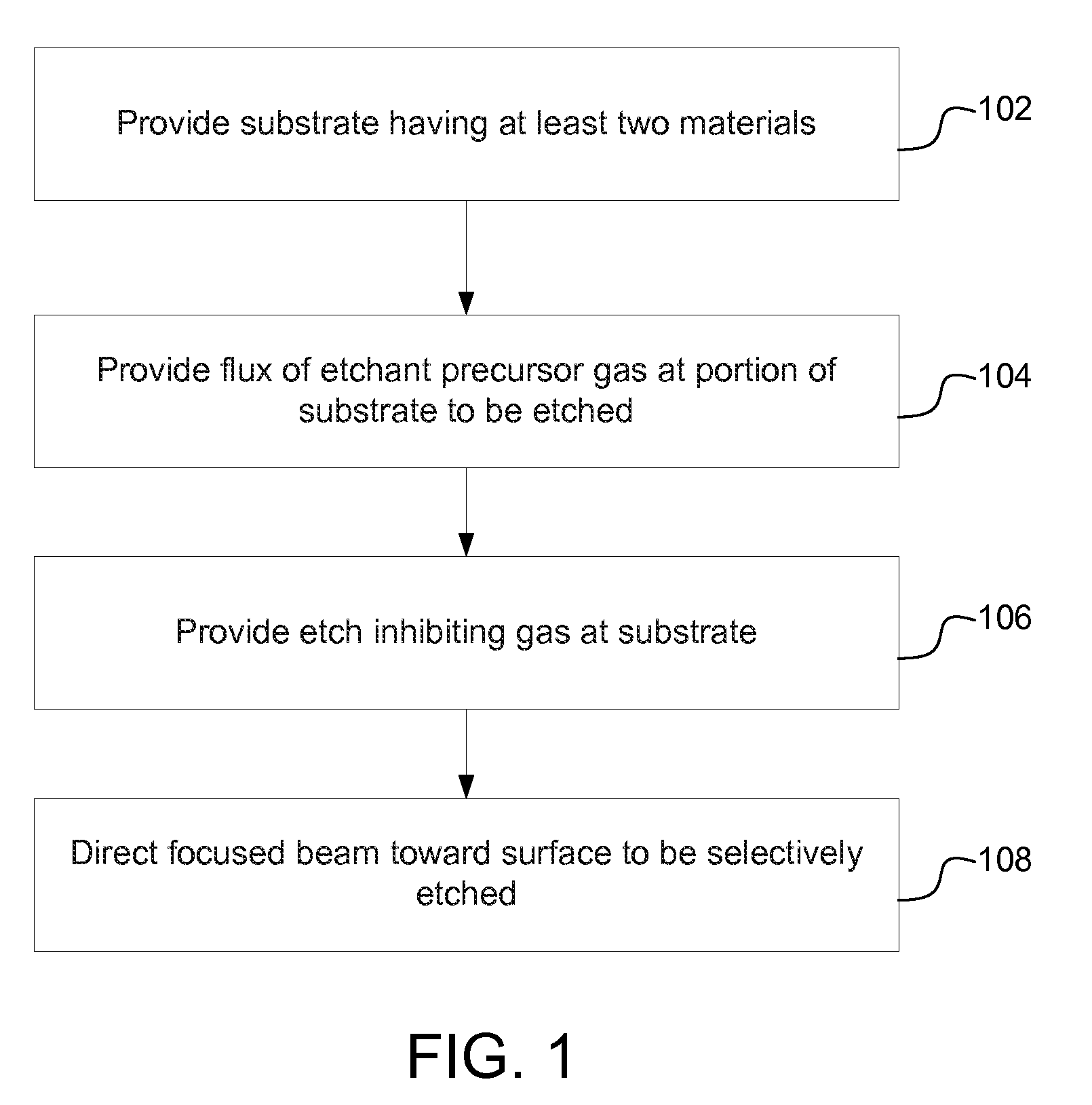
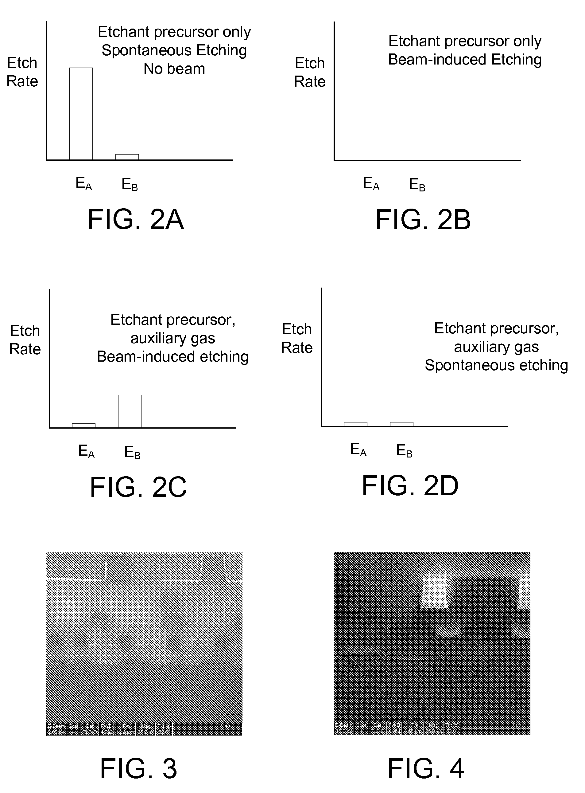
[0019]Embodiments of the invention provides a method and apparatus for selectively processing materials on a substrate using a focused beam, such as an electron beam, ion beam, neutral particle beam, or laser beam. Using a finely focused beam allows a user to precisely control the region to be processed. For example, modern electron beams can be focused to a spot size of a few nanometers and can be scanned over a region on the order of nanometers up to millimeters. During electron beam processing, a substrate typically has multiple materials exposed to the precursor gases or to the beam. In one preferred embodiment, competing reactions, both spontaneous and beam-induced, favor etching of a first material over etching of one or more other exposed materials. Thus, those embodiments preferentially etch the first material, while preserving or minimizing damage to the other exposed materials.

[0020]In some embodiments, two precursor gases are introduced into the region of the work piece. ...


PUM


Abstract

A method and apparatus for selective etching a substrate using a focused beam. For example, multiple gases may be used that are involved in competing beam-induced and spontaneous reactions, with the result depending on the materials on the substrate. The gases may include, for example, an etchant gas and an auxiliary gas that inhibits etching.

Description

TECHNICAL FIELD OF THE INVENTION[0001]The present invention relates to selective etching using a focused beam, and is particularly applicable to electron beam imaging of cross sections of multi-layered structures.BACKGROUND OF THE INVENTION[0002]Modern integrated circuits are typically made of multiple layers of materials, such as metals, semiconductors, and insulators, fabricated on semiconductor substrates. To characterize the fabrication process or investigate process problems in semiconductor manufacturing, process engineers often use a focused ion beam to cut a cross section of the integrated circuit and then use a scanning electron microscope to view the edges of the layer in the cross section. For example, process engineers may cut cross sections to observe integrated circuit features, such as poly-silicon gates, amorphous silicon, and various dielectrics and barrier materials and to measure the layer thickness and uniformity.[0003]A scanning electron microscope forms an imag...

Claims


Application Information

Patent Timeline
IPC IPC(8): H01L21/306
CPCH01L21/3065H01L21/306H01L21/32137H01L21/31116
Inventor RANDOLPH, STEVENCHANDLER, CLIVE D.
Owner FEI COMPANY
Why Eureka
Try Eureka