Superconducting wire with low ac losses

a superconducting wire and low loss technology, applied in the direction of superconductors/hyperconductors, superconductors/coils, magnetic bodies, etc., can solve the problems of limiting the economic justification of superconductors, unable to apply, and loss during field changes, etc., to achieve the effect of small width

Inactive Publication Date: 2010-08-05
NEXANS
View PDF9 Cites 21 Cited by
  • Summary
  • Abstract
  • Description
  • Claims
  • Application Information

AI Technical Summary

Problems solved by technology

Even in applications with DC currents (DC magnets, synchronous motors), losses occur during field changes, when currents are ramped sometimes very quickly.
These losses can be so high, that heat build-up in a component heats the winding to above its safe operating limit causing the device failure.
AC losses are therefore the key bottleneck to the wider application of HTS superconductors, often limiting the economic justification of superconductors or even completely rendering an application impossible.
(1) Eddy current losses in normal metals caused by time varying magnetic fields. Normal metal is used in every technical superconducting wire as a base or matrix material stabilising a superconductor mechanically and electrically.
(2) Hysteretic losses in the superconductor are caused by magnetic flux lines (vortices) entering and leaving the superconductor as it swings through an AC cycle. In a simplified model losses are proportional to the change in magnetization ΔM˜Jc×r, where Jc is the critical current, and r is the characteristic size of superconductor. The hysteretic losses can be reduced by breaking up the superconductor into small filaments, and bundling the filaments in a metallic matrix. This approach is well known and efficient in Low Temperature Superconductors (LTS), whereas, for example, thin filaments (from submicron thickness up to about 100 μm, depending on application) of Niobium-Titanium wire are embedded in a Copper matrix. This is called a composite wire.
(3) Coupling losses occur in composite wires due to eddy currents in the matrix effectively short circuiting the superconducting filaments. In effect this very much reduces the positive effect of splitting up a superconductor into filaments in the first place. As an effective countermeasure against coupling losses, the composite wire is twisted along its length with a twist pitch on the order of centimetres. Thus filaments change position in the ac field and the inductive voltage caused by eddy currents in the superconductor is changing sign with twist pitch length, effectively zeroing out this loss contribution.
The problem here is that, typically buffer layer(s) and ceramic oxide superconductors such as YBCO cannot withstand mechanical deformation beyond narrow limits without damage.
Unfortunately, this solution does not effectively reduce losses, as coupling losses through the connective coating remain dominant.
As a practical conductor suitable for winding a coil this is ineffective, as the twists build up conductor thickness like a tie and thus do not fill space efficiently and make winding a coil or other components therefrom nearly impossible.
This, being an efficient reduction of losses, is a challenging production process.
While this reduces losses in a wide tape efficiently, the width of each tape is still a couple of millimetres, thus not reducing losses far enough for many applications.

Method used


Image

  • Superconducting wire with low ac losses
  • Superconducting wire with low ac losses
  • Superconducting wire with low ac losses

Examples


Embodiment Construction

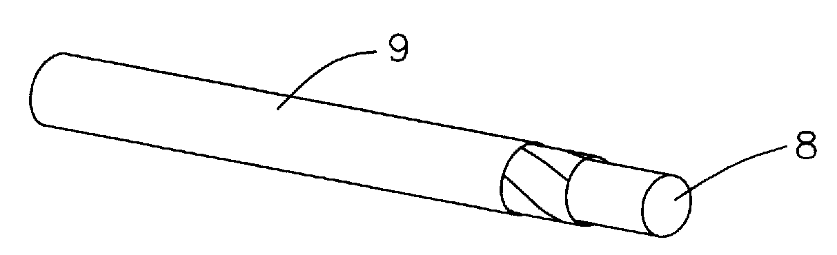
[0041]FIGS. 4 and 5 show two examples of the superconducting wire 7 of the present invention.

[0042]As can be seen in FIGS. 4 and 5 the superconducting wire 7 has essentially a round (tubular) shape with the HTS-layer 3 being provided on the outer surface. The HTS layer 3 is patterned into a screw line snaking around the length of superconductor wire 7.

[0043]The width and twist pitch of the spiral pathway can be optimized according to the need of the respective application.

[0044]As shown in FIG. 6 the HTS-layer 3 can be patterned into one or more parallel lanes 15 snaking around the length of the wire side by side.

[0045]According to the present invention very small widths of the lanes are obtainable.

[0046]By the provision of individual lanes the HTS superconductor is separated into smaller filaments wherein for reducing AC losses adjacent filaments (e.g. lanes) are not in contact with each other. Consequently, a gap 16 is formed between adjacent lanes 15.

[0047]For the present inventi...


PUM

PropertyMeasurementUnit
frequencyaaaaaaaaaa
frequencyaaaaaaaaaa
temperatureaaaaaaaaaa

Abstract

A multilayer superconducting wire 7 with essentially round cross sectional area where the outer surface of the round wire is provided with a high temperature superconductor layer 3 and where at least the high temperature superconductor layer 3 is fabricated as a spiral running along the length of the superconductor wire 7 in parallel lanes 15.

Description

RELATED APPLICATION[0001]This application claims the benefit of priority from EP 08 305 235.7, filed on Jun. 5, 2008, the entirety of which is incorporated by reference.BACKGROUND[0002]1. Field of the Invention[0003]The present invention relates to a multilayer superconducting wire composed of a substrate of long length, such as a tape, onto which a layer of super-conducting material is deposited.[0004]In particular the present invention relates to such a multilayer superconducting wire also referred to “coated conductor” and having an essentially round cross section.[0005]2. Related Art[0006]Superconducting wires are known to carry DC currents of extraordinary high current density with very low losses. For many application in the energy industry there is a need to carry large AC currents of typically 50 Hz or 60 Hz frequency.[0007]There are a number of known loss mechanisms in superconductors, which effectively lead to dissipation of heat in a superconducting wire. As superconducto...

Claims


Application Information

Patent Timeline
Patent Type & Authority Applications(United States)
IPC IPC(8): H01B12/04H01L39/24
CPCY10T29/49014H01L39/2419H01L39/2464H01L39/143H10N60/203H10N60/0268H10N60/0661
Inventor STEINMEYER, FLORIANRIKEL, MARKEHRENBERG, JURGENELSCHNER, STEFFEN
Owner NEXANS
Why Eureka
Try Eureka