Tile gap seal assembly and method

a sealing assembly and tile technology, applied in the field of thermal protection systems, can solve the problems of affecting the overall utility of the seal, the difficulty of repairing and/or replacing the seal assembly or the tile, and the hardening compound applied over the filler bar

Active Publication Date: 2010-08-12
THE BOEING CO
View PDF33 Cites 46 Cited by
  • Summary
  • Abstract
  • Description
  • Claims
  • Application Information

AI Technical Summary

Benefits of technology

[0020]In an embodiment of the seal assembly, the bulb jacket and the web may be formed of woven material such as ceramic material including, but not limited to, a ceramic composition such as ceramic material that is available from the 3M Company and which is commercially-known as Nextel 312 having an alumina-boria-si...

Problems solved by technology

While the above described prior art sealing assembly configurations are generally suitable for their intended purposes, they possess several drawbacks which detract from their overall utility.
For example, the hardening compound that is applied over filler bar complicates removal, repair and/or replacement of the tiles.
Likewise, seal assemblies which are a...

Method used


Image

  • Tile gap seal assembly and method
  • Tile gap seal assembly and method
  • Tile gap seal assembly and method

Examples


Embodiment Construction

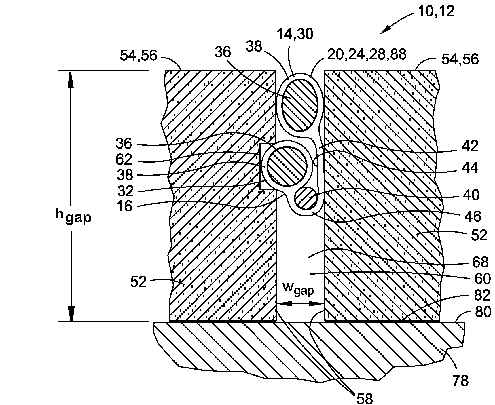
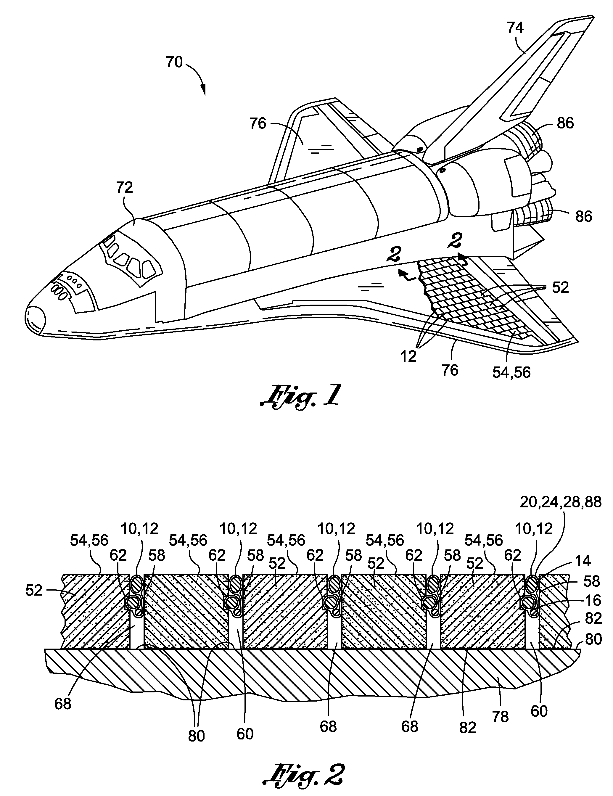
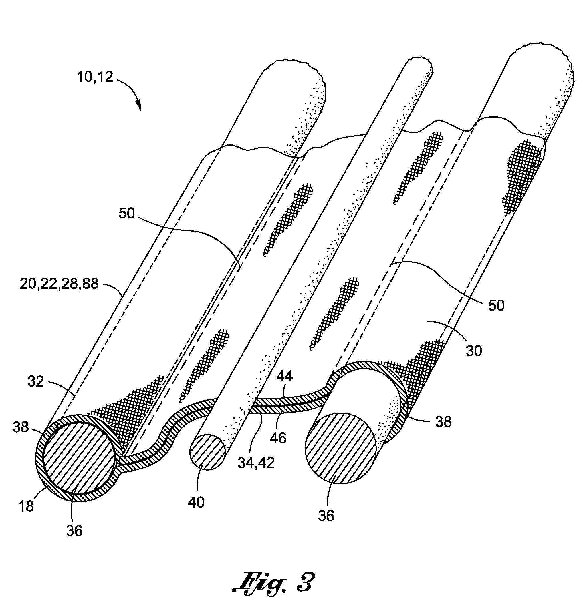
[0035]Referring now to the drawings wherein the showings are for purposes of illustrating preferred and various embodiments of the disclosure only and not for purposes of limiting the same, shown in FIG. 1 is a perspective illustration of a vehicle 70 which may employ one or more seal assemblies 12 for sealing tile gaps 60 between adjacently disposed tiles 52. The seal assembly 12 as disclosed herein may be installed within tile gaps 60 of tiles 52 mounted on a substructure 78 such as an airframe substructure 78 of the vehicle 70 illustrated in FIG. 1.

[0036]However, the seal assembly 12 may be installed within tile gaps 60 of tiles 52 that may be used in any application including, but not limited to, external surfaces of vehicles, internal surfaces of engines such as combustion chambers and nozzles in turbine and ramjet engines and nozzles in rocket engines as well as other high temperature environments. In this regard, the seal assembly 12 may be installed within tile gaps 60 of ti...


PUM


Abstract

A seal assembly is configured to seal a tile gap between a pair of tiles. Each of the tiles may include a tile side surface. At least one of the tiles may include a groove which may be formed along a length of the tile side surface. The seal assembly may comprise a gasket assembly including first and second bulb portions which may be interconnected by a web. A spacer rope may be positionable along the web. The gasket assembly may define a folded configuration for mounting within the tile gap when the web is wrapped around the spacer rope such that the second bulb portion is positioned between the spacer rope and the first bulb portion. The second bulb portion may be receivable within the groove.

Description

CROSS-REFERENCE TO RELATED APPLICATIONS[0001](Not Applicable)STATEMENT RE: FEDERALLY SPONSORED RESEARCH / DEVELOPMENT[0002](Not Applicable)FIELD[0003]The present disclosure relates generally to thermal protection systems and, more particularly, to a seal assembly and method for sealing gaps between tiles.BACKGROUND[0004]Thermal protection systems are employed in a wide variety of applications including, but not limited to, interior surfaces of jet and rocket engines and exterior surfaces of vehicles for protection against hot, convective flow passing over the vehicle. For example, a thermal protection system (TPS) may be applied to hypersonic vehicles and reusable launch vehicles to provide a thermal shield against extreme temperatures to which the vehicle is subjected. As applied to reusable launch vehicles, a TPS must be capable of protecting the vehicle substructure against temperature extremes ranging from −300° F. on orbit to 3000° F. during re-entry into the Earth's atmosphere. ...

Claims


Application Information

Patent Timeline
IPC IPC(8): E04B1/68E04B1/66B60J10/00
CPCE04B1/948B64G1/58Y10S277/921
Inventor BEHRENS, WILLIAM W.TUCKER, ANDREW R.
Owner THE BOEING CO
Why Eureka
Try Eureka