
Time-of-flight sensor-assisted iris capture system and method

Active Publication Date: 2010-08-12
ROBERT BOSCH GMBH
View PDF7 Cites 23 Cited by
  • Summary
  • Abstract
  • Description
  • Claims
  • Application Information

AI Technical Summary

Benefits of technology

[0013]An advantage of the present invention is that it provides an extended depth of field (DOF), an enlarged capture volume, and an improved capturing speed.
[0014]Another advantage is that a time-of-flight (TOF) sensor is used in the iris capture system, which provides accurate depth information from the depth map and allows the system to locate the three-dimensional eye position accurately so that the iris / face can be captured accurately.
[0015]Yet another advantage is that the accurate depth information provided by a TOF sensor can allow the system to perform fast capture as the focus position can be quickly calculated for cameras with adjustable focus. In contrast, autofocus is usually slow in this case.
[0016]Still another advantage is that the depth information provided by the TOF sensor can be used to estimate the blur kernel for the iris deblurring. Defocus blur can easily occur in such systems, which is an issue that can seriously affect the system performance.
[0017]A further advantage is that the depth information provided by the TOF sensor for the subject's face may be used to estimate the three-dimensional geometry of the subject's face, which can enable a low cost face recognition system including multimodal (i.e., three-dimensional face shape and iris) integration.
[0018]A still further advantage is that the TOF sensor allows a compact and portable design for iris capture for many security applications (e.g., access control or border control).

Problems solved by technology

However, the depth of field (DOF) for each user is limited (e.g., five to twelve centimeters).
Because the acquired depth information based on these methods is not very accurate, these systems are not robust enough for practical use.
For example, the feature matching in the stereo cameras is not always accurate under different lighting conditions.
As a result, the robust sub-pixel matching is not easy to achieve in practice.
High accuracy would require a longer baseline, which make it impossible to build a compact iris capture system for many security applications.
This is because defocus blur can easily happen when a moving subject is captured with a significant amount of system delay because of the slow movements of the pan-tilt unit or because of a long autofocus time.
Defocus blur can easily occur in such systems, which is an issue that can seriously affect the system performance.

Method used


Image

  • Time-of-flight sensor-assisted iris capture system and method
  • Time-of-flight sensor-assisted iris capture system and method
  • Time-of-flight sensor-assisted iris capture system and method

Examples


Embodiment Construction

[0033]The embodiments hereinafter disclosed are not intended to be exhaustive or limit the invention to the precise forms disclosed in the following description. Rather the embodiments are chosen and described so that others skilled in the art may utilize its teachings.

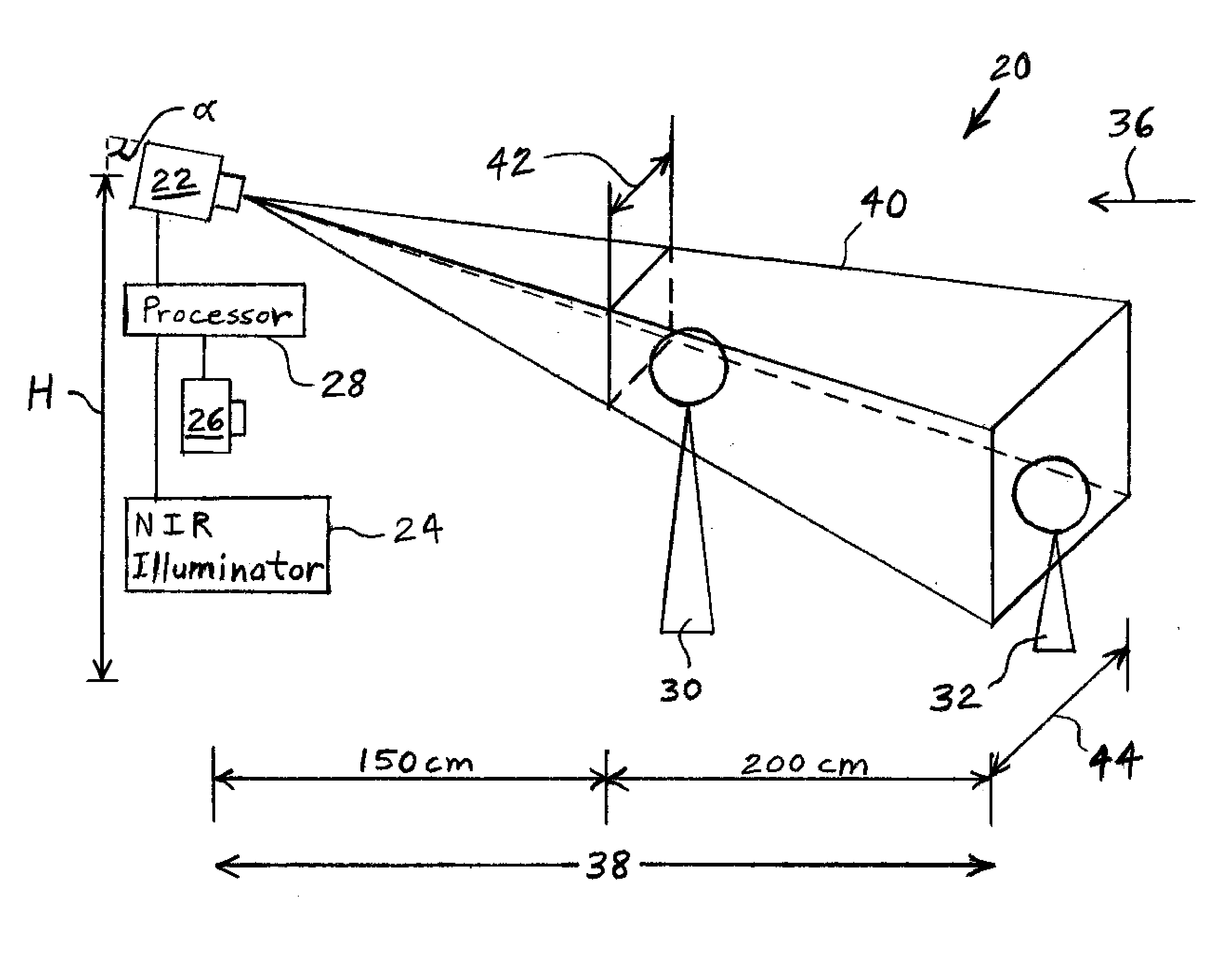
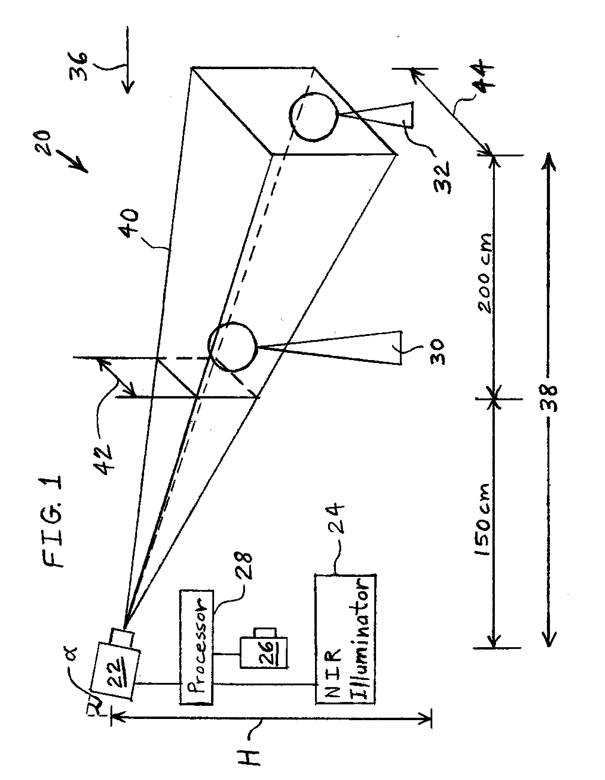
[0034]Turning now to the drawings, and particularly to FIG. 1, there is shown one embodiment of an iris capture system 20 of the present invention including an NFOV NIR camera 22 with adjustable focus, an NIR illuminator 24, and a depth sensor 26 all in electronic communication with a central processor 28. System 20 may capture images of, and detect the positions of, moving subjects such as a human being 30 or a human being 32 when he approaches a doorway at which camera 22, illuminator 24 and sensor 26 are mounted, such as in a direction indicated by arrow 36. Camera 22 may be installed with a mounting height H and tilt angle α such that a standoff distance 38 for the user is approximately between 1.5 meters and 3.5 ...


PUM


Abstract

A method of identifying a living being includes using a time-of-flight sensor to determine a location of a face of the living being. An image of an iris of the living being is produced dependent upon the location of the face as determined by the time-of-flight sensor. The produced image is processed to determine an identity of the living being.

Description

BACKGROUND[0001]1. Field of the Invention[0002]The present invention relates to apparatuses and methods for identifying personnel and, more particularly, to apparatuses and methods for identifying personnel based on visual characteristics of the irises of their eyes.[0003]2. Description of the Related Art[0004]Iris recognition, or “iris capture” is a method of biometric personal identification that uses pattern recognition algorithms based on images of at least one of the irises of an individual's eyes. Iris recognition uses camera technology to produce images of the details of the iris. These images are converted into digital templates and provide mathematical representations of the iris that are used to identify individuals.[0005]Many iris capture systems with low levels of intrusiveness have been proposed to extend the operational range for iris capture in recent years. For example, a system has been proposed that consists of multiple synchronized high-speed, high-resolution, and...

Claims


Application Information

Patent Timeline
IPC IPC(8): G06K9/00H04N5/232
CPCG06K9/00604G06V40/19
Inventor REN, LIUHUANG, XINYUYANG, RUIGANG
Owner ROBERT BOSCH GMBH
Learn More