
Small caliber implantable biometric leads and cables for same

a biometric and small caliber technology, applied in the direction of cables, insulated conductors, therapy, etc., can solve the problems of decreasing the ability to carry large currents and increasing the dc resistance of cables, so as to optimize mechanical and electrical performance, reduce the diameter of leads, and optimize mechanical and electrical properties

Active Publication Date: 2010-08-12
PACESETTER INC
View PDF10 Cites 21 Cited by
  • Summary
  • Abstract
  • Description
  • Claims
  • Application Information

AI Technical Summary

Benefits of technology

The present cable and lead designs provide optimal mechanical and electrical performance for applications such as ICTD leads. The designs reduce the diameter of leads while maintaining optimized mechanical and electrical properties. This is achieved through multiple strategies such as reducing the diameters of conducting cables, using oval cross-sectional areas for increased contact surface between filaments, and employing non-conductive coatings or jackets to reduce fretting fatigue. The cross-sectional area of filaments decreases as they are positioned at increasing radial distance from the center of the cable, which contributes to both structural strength and flexibility of the cable. The relative composition of various metals and / or alloys of filaments in the cable is varied in relation to different radial distances of the filaments from the center of the cable. These designs provide a thinner cable with optimized mechanical and electrical properties.

Problems solved by technology

Also, when the lead size becomes smaller, the DC resistance of the cable increases, which in turn decreases the capability to carry large currents.

Method used


Image

  • Small caliber implantable biometric leads and cables for same
  • Small caliber implantable biometric leads and cables for same
  • Small caliber implantable biometric leads and cables for same

Examples


Embodiment Construction

Overview

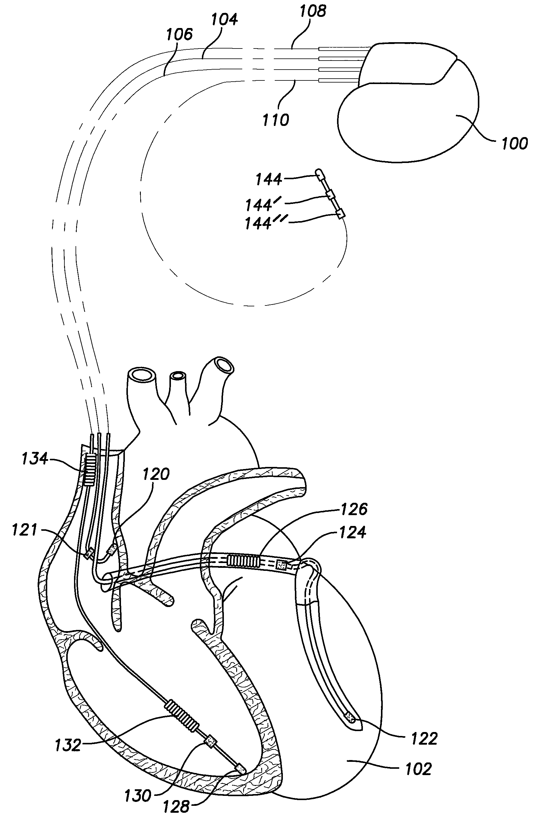
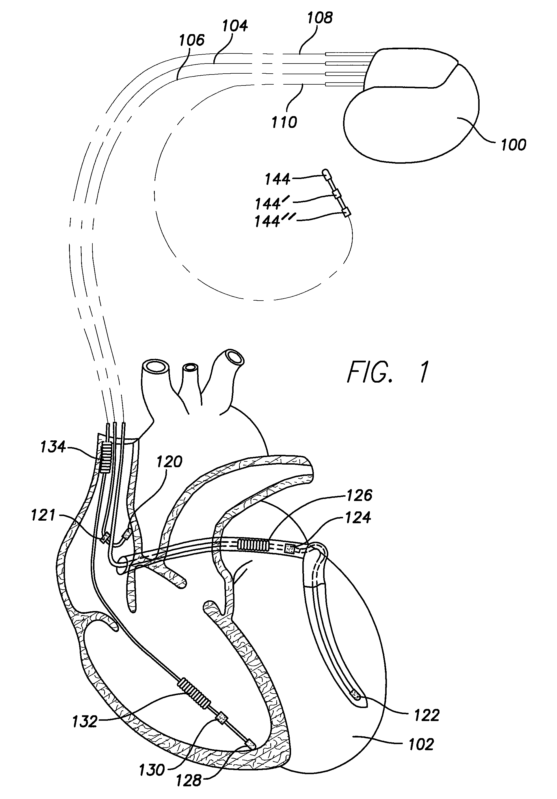
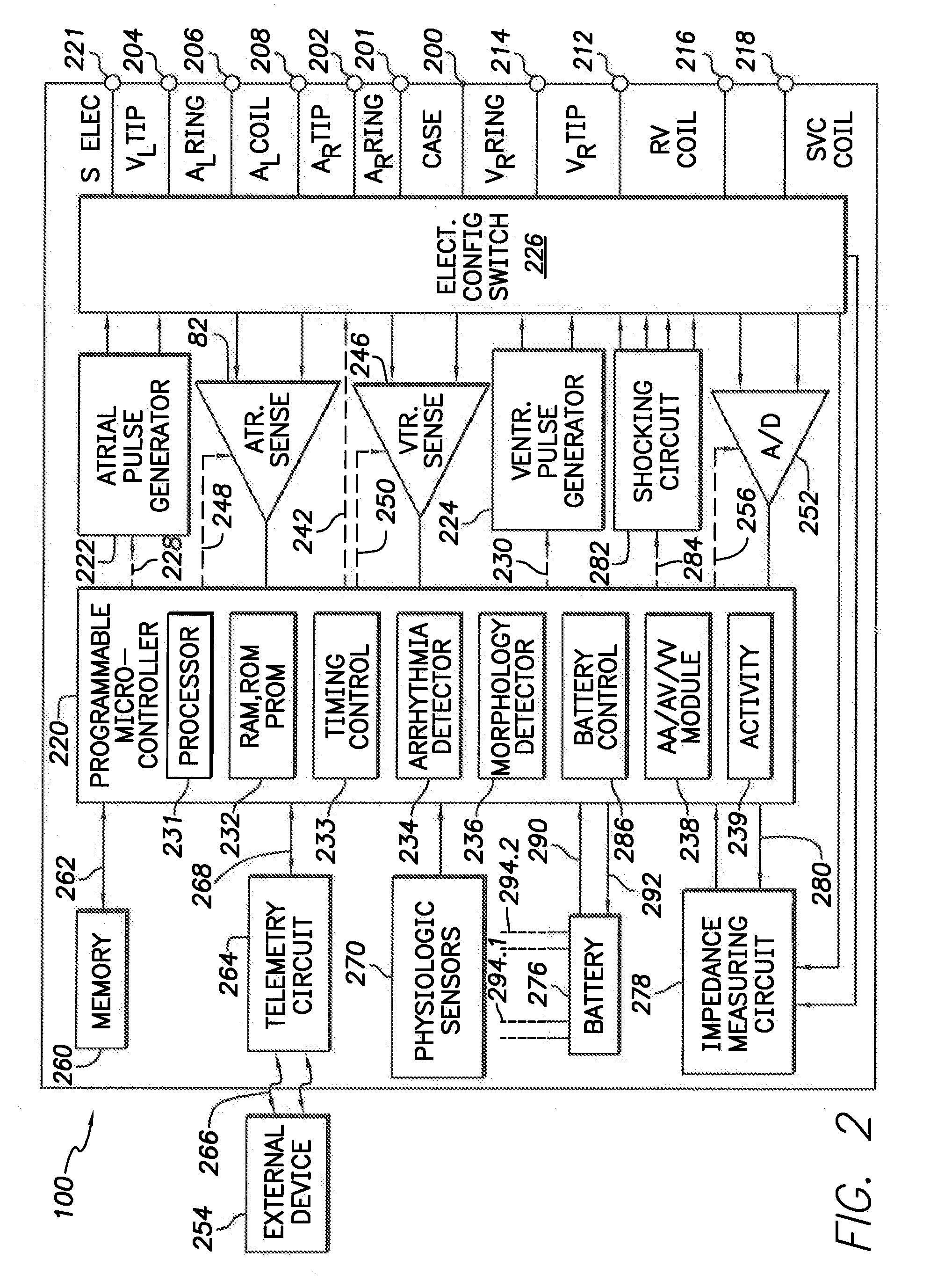
[0055]The following detailed description of systems and methods for conductor cable designs of small caliber ICTD leads for an implantable cardiac therapy device refers to the accompanying drawings that illustrate exemplary embodiments consistent with these systems and methods. Other embodiments are possible, and modifications may be made to the embodiments within the spirit and scope of the methods and systems presented herein. Therefore, the following detailed description is not meant to limit the methods and systems described herein. Rather, the scope of these methods and systems is defined by the appended claims.

[0056]It would be apparent to one of skill in the art that the systems and methods for conductor cable designs of small caliber ICTD leads for an implantable cardiac therapy device, as described below, may be implemented in many different embodiments of hardware, materials, construction methods, and / or the entities illustrated in the figures. Any actual hardware,...


PUM

PropertyMeasurementUnit
sizeaaaaaaaaaa
voltagesaaaaaaaaaa
voltagesaaaaaaaaaa

Abstract

Implantable medical leads have reduced diameter while providing for optimized mechanical and electrical properties, by reducing the diameters of the conducting cables used within the leads for sensing and delivery of therapeutic electrical stimulation. In an embodiment, conducting filaments within a cable have oval cross-sectional areas. Suitably orienting the oval filaments increases the contact surface between adjacent filaments, broadly distributing the pressure between filaments and reducing fretting fatigue, while the oval cross-sectional area also increases conductivity. In an embodiment, non-conducting coatings around filaments within a cable, or around groups of filaments organized into cable-layers, reduce fretting fatigue. In an embodiment, the cross-sectional area of filaments decreases as the filaments are positioned at increasing radial distances from the center of the cable. In an embodiment, the relative composition of various filament metals and / or alloys is varied in filaments at different radial distances from the center of the cable.

Description

FIELD OF THE INVENTION[0001]The present invention relates generally to implantable cardiac therapy devices, and more specifically to implantable leads for implantable cardiac devices.BACKGROUND[0002]Implantable cardiac therapy devices (ICTDs) enjoy widespread use for providing convenient, portable, sustained therapy for cardiac patients with a variety of cardiac arrhythmias. ICTDs may combine a pacemaker and defibrillator in a single implantable device. Such devices may be configured to provide ongoing cardiac pacing in order to maintain an appropriate cardiac rhythm. In addition, should the ICTD detect that the patient is experiencing an episode of ventricular fibrillation (or an episode of ventricular tachycardia), the ICTD can deliver appropriate defibrillation therapy.[0003]Cardiac rhythm management (CRM) therapies require not only an ICTD, but also the placement of electrical leads threaded through blood vessels and typically into the heart itself. Patients with implanted elect...

Claims


Application Information

Patent Timeline
Patent Type & Authority Applications(United States)
IPC IPC(8): A61N1/05H01B7/00
CPCA61N2001/086A61N1/05A61N1/086
Inventor ZHAO, YONG D.
Owner PACESETTER INC
Learn More