Tray, tray support member, and vacuum processing apparatus

Active Publication Date: 2010-08-19
CANON ANELVA CORP
View PDF6 Cites 12 Cited by
  • Summary
  • Abstract
  • Description
  • Claims
  • Application Information

AI Technical Summary

Benefits of technology

[0008]It is an object of the present invention to provide a tray and tray support member which increase the productivity by preventing the positional deviations of th

Problems solved by technology

However, if the large-sized tray capable of holding a number of substrates is used in the vacuum processing apparatus of Japanese Patent Laid-Open No. 2002-43404, the deformation of the tray caused by the temperature change is no longer negligible.
That is, the warpage of the tray ch

Method used


Image

  • Tray, tray support member, and vacuum processing apparatus
  • Tray, tray support member, and vacuum processing apparatus
  • Tray, tray support member, and vacuum processing apparatus

Examples


first embodiment

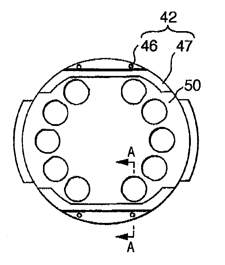
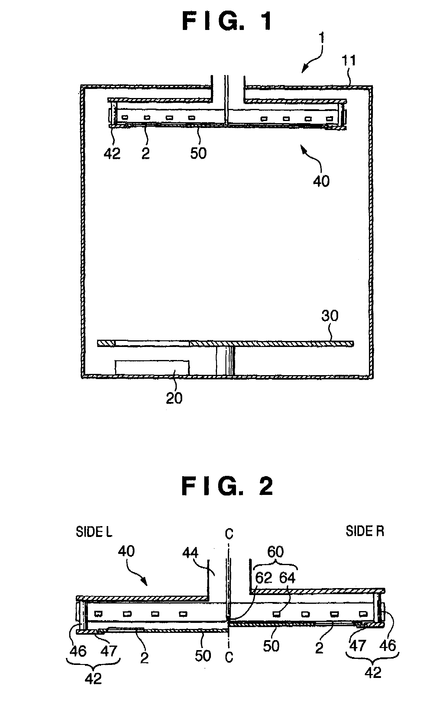
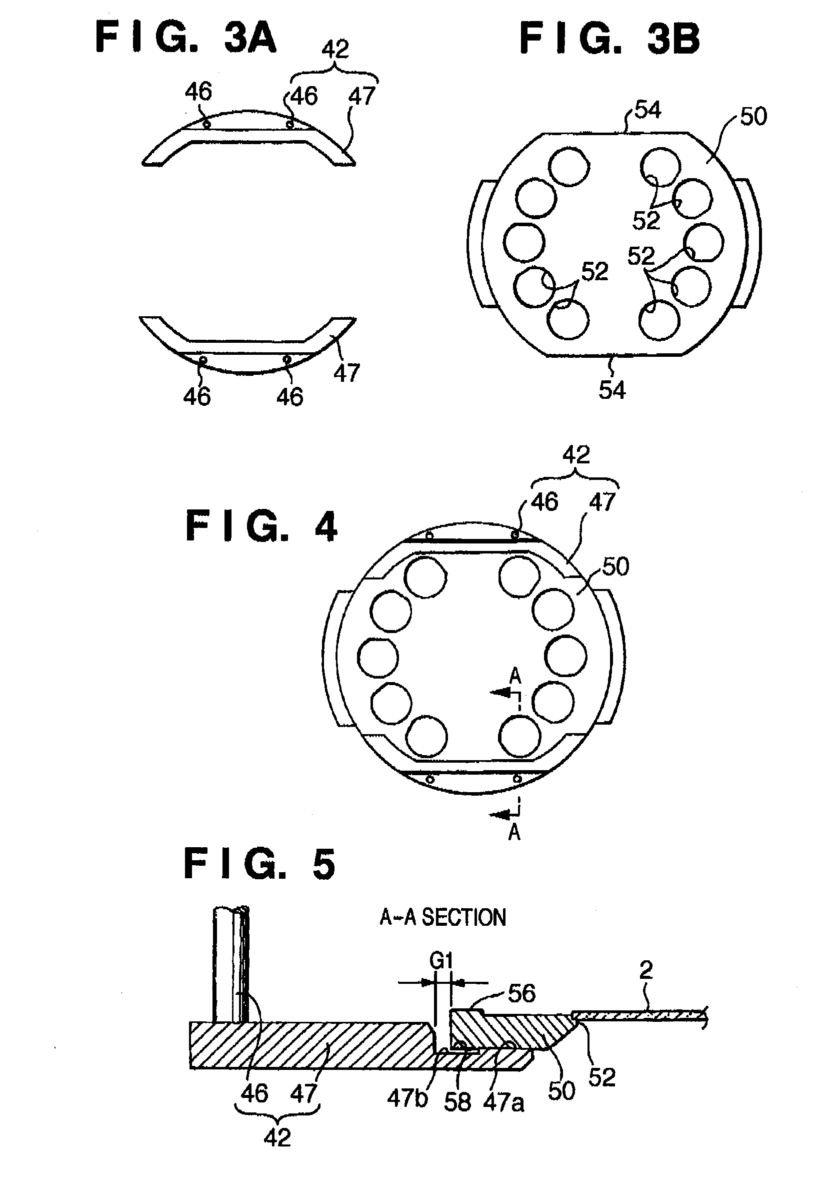
[0037]FIGS. 1 to 5 are views for explaining a vacuum processing apparatus according to the first embodiment of the present invention. FIG. 1 is a schematic sectional view of the vacuum processing apparatus. FIG. 2 is an enlarged schematic sectional view of a holder. FIGS. 3A and 3B are front views of a tray and chucks. FIG. 4 is a front view of the state in which the tray is supported by the chucks. FIG. 5 is a sectional view taken along a line A-A in FIG. 4. Note that some portions are not shown in these drawings in order to avoid complicating them.

[0038]The vacuum processing apparatus according to the present invention is widely applicable to a sputtering deposition apparatus, thin film formation (a PVD apparatus) using an electron beam or the like, or vacuum processing such as surface modification or dry etching. In this embodiment, however, an example (vacuum processing apparatus 1) in which the vacuum processing apparatus is applied to a sputtering deposition apparatus will be ...

second embodiment

[0069]FIGS. 6A to 6C, 7A, 7B, and 8 are views for explaining a vacuum processing apparatus according to the second embodiment of the present invention. FIGS. 6A to 6C are front views of a tray and chucks. FIGS. 7A and 7B are front views of the state in which the tray is supported by the chucks. FIG. 8 is a sectional view taken along a line B-B in FIG. 7B. Note that some portions are not shown in these drawings in order to avoid complicating them.

[0070]In the following embodiment, the same reference numerals denote, for example, the same members and arrangements as in the first embodiment, and a repetitive explanation will be omitted.

[0071]The vacuum processing apparatus according to this embodiment differs from that of the first embodiment in the structure of a tray.

[0072]A tray 70 of this embodiment is obtained by combining an inner tray 71 and outer tray 72.

[0073]As shown in FIG. 6B, the inner tray 71 is a disk-like member having a number of substrate mounting portions 52, and mad...


PUM


Abstract

A chuck capable of holding a tray capable of holding a substrate in a predetermined position in a vacuum vessel includes a vertically movable frame, and an arm extending from the frame toward the tray and capable of supporting the tray. The arm includes a support portion which abuts against the tray, and a counterbore portion formed on that side of the support portion which faces the frame. This structure can reduce the warpage of the tray.

Description

BACKGROUND OF THE INVENTION[0001]1. Field of the Invention[0002]The present invention relates to a tray and tray support member for performing vacuum processing such as thin film formation, surface modification, or dry etching, and a vacuum processing apparatus including the tray and tray support member. The present invention particularly relates to a tray and tray support member having a function capable of controlling the temperature of an object (substrate) to be processed while the object is held on the tray, and a vacuum processing apparatus including the tray and tray support member.[0003]2. Description of the Related Art[0004]Conventionally, a vacuum processing apparatus including a tray to be used to transfer an object (substrate) to be processed and capable of controlling the substrate held on the tray to a predetermined temperature by supplying a temperature transmission gas (heating gas) to a space on the back side of the substrate is known (see, for example, Japanese Pat...

Claims


Application Information

Patent Timeline
IPC IPC(8): C23F1/08B65D1/34B65D25/00C23C14/00
CPCH01L21/68728H01L21/68721H01L21/02H01L21/68H01L21/683
Inventor HIROMI, TAICHIMURAKAMI, TADAAKI
Owner CANON ANELVA CORP
Why Eureka
Try Eureka