2D/3D switchable integral imaging systems

a technology of integral imaging and switchable parts, applied in optics, instruments, electrical equipment, etc., can solve the problems of difficult to transmit and/or reproduce images in real-time using holographic methods, difficult to realize large objects, and limited practical application of holographic methods

Active Publication Date: 2010-08-19
SAMSUNG ELECTRONICS CO LTD
View PDF2 Cites 17 Cited by
  • Summary
  • Abstract
  • Description
  • Claims
  • Application Information

AI Technical Summary

Benefits of technology

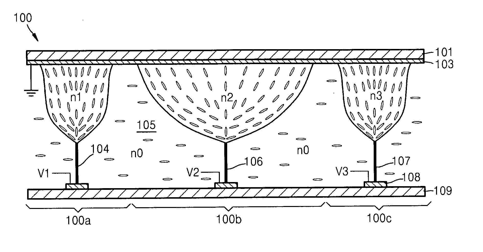
[0011]Example embodiments may include a two dimensional (2D) / three dimensional (3D) switchable integral imaging system that is capable of recording image information from an object without distortion according to positions, reproducing the recorded image information without distortion by actively varying a focal point of a lens array, and / or displaying 2D images as well.

Problems solved by technology

However, holographic methods may use a coherent light source and / or may have difficulty in realizing a large object located at a long distance.
Also, due to the large amount of data involved, it may be difficult to transmit and / or reproduce images in real-time using holographic methods.
Thus, practical applications of holographic methods may be limited.
However, since left and right images may be formed on one screen, the resolution of the images may be reduced by a half or more, and / or visual fatigue may be generated due to a difference in parallax between the two images shown to the eyes of a person and the focusing capability of the person.
Thus, it may be difficult to see a 2D image due to the structure of the system using stereoscopic methods.
However, integral imaging methods may not have been observed much in the past due to limitations in imaging devices and / or display devices, but may have been researched more recently with the development of high resolution imaging devices and / or high resolution displays.
However, since a lens array having a fixed focal point may be used in integral imaging methods, image information obtained from an object may be distorted according to positions and may be recorded in that manner, so integral imaging methods may only be used to display 3D images.

Method used


Image

  • 2D/3D switchable integral imaging systems
  • 2D/3D switchable integral imaging systems
  • 2D/3D switchable integral imaging systems

Examples


Embodiment Construction

[0030]Example embodiments will now be described more fully with reference to the accompanying drawings. Embodiments, however, may be embodied in many different forms and should not be construed as being limited to the embodiments set forth herein. Rather, these example embodiments are provided so that this disclosure will be thorough and complete, and will fully convey the scope to those skilled in the art. In the drawings, the thicknesses of layers and regions are exaggerated for clarity.

[0031]It will be understood that when an element is referred to as being “on,”“connected to,”“electrically connected to,” or “coupled to” to another component, it may be directly on, connected to, electrically connected to, or coupled to the other component or intervening components may be present. In contrast, when a component is referred to as being “directly on,”“directly connected to,”“directly electrically connected to,” or “directly coupled to” another component, there are no intervening comp...


PUM

PropertyMeasurementUnit
voltageaaaaaaaaaa
voltagesaaaaaaaaaa
refractive index distributionaaaaaaaaaa

Abstract

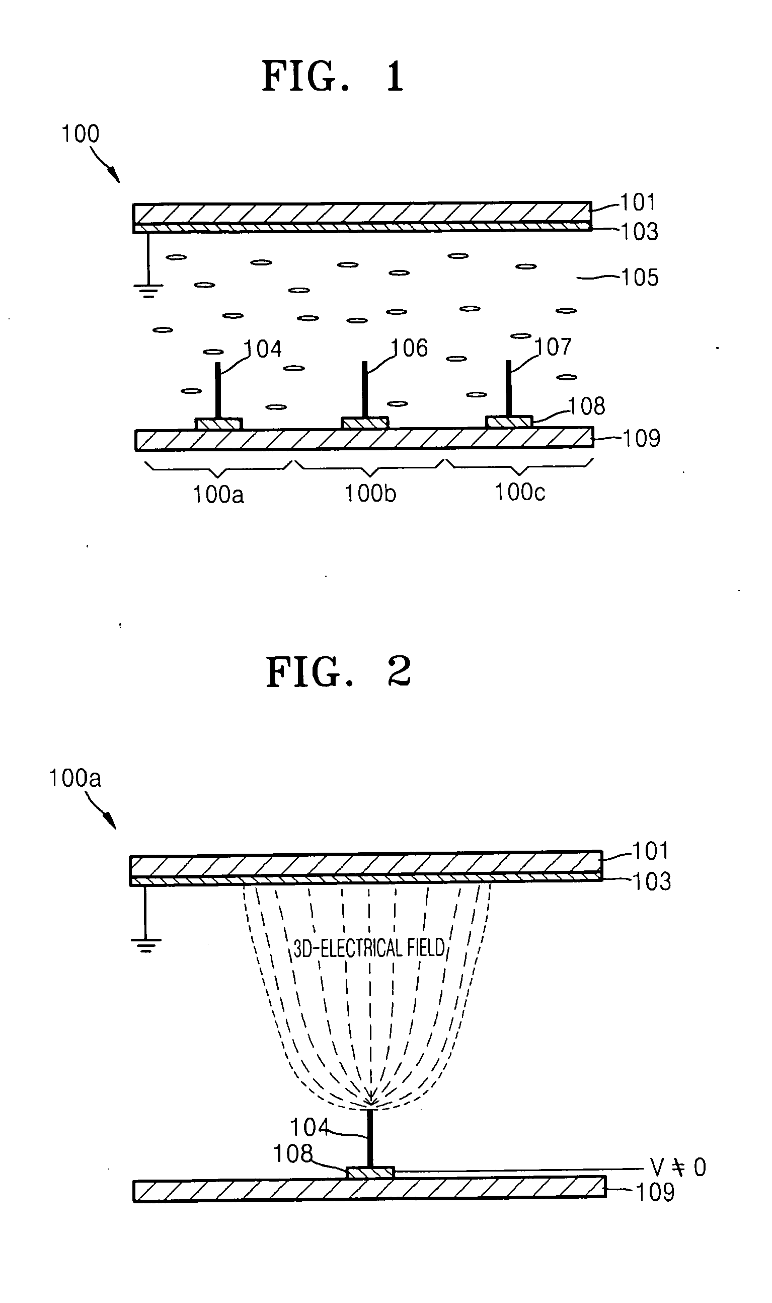
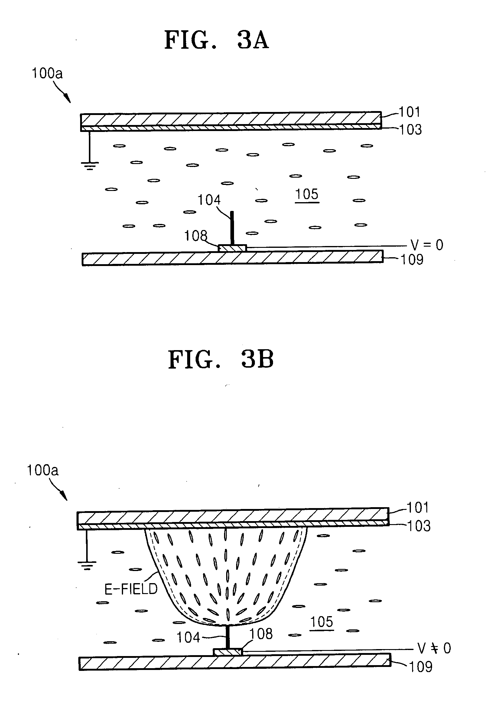
An integral imaging system may include a lens unit. The lens unit may include a first substrate; a second substrate; a first electrode on the first substrate; a second electrode on the second substrate; a liquid crystal layer between the first and second substrates; and an array of nanostructures protruding from the first substrate into the liquid crystal layer. The first and second electrodes may be configured to apply one or more voltages to the array of nanostructures. When the one or more voltages are applied to the array of nanostructures, one or more electric fields may be formed between the array of nanostructures and the second electrode, varying an arrangement of molecules in the liquid crystal layer and forming a refractive index distribution in the liquid crystal layer.

Description

CROSS-REFERENCE TO RELATED APPLICATIONS[0001]This application claims priority from Korean Patent Application No. 10-2009-0013503, filed on Feb. 18, 2009, in the Korean Intellectual Property Office (KIPO), the entire contents of which are incorporated herein by reference.BACKGROUND[0002]1. Field[0003]Example embodiments relate to two dimensional (2D) / three dimensional (3D) switchable integral imaging systems capable of displaying 3D images and / or 2D images.[0004]2. Description of the Related Art[0005]Recently, stereoscopic image display apparatuses may have been used in various fields such as medical imaging, games, advertisements, education, military applications, etc. Methods of displaying stereoscopic images such as holographic methods, stereoscopic methods, integral imaging methods, and so forth may be being researched.[0006]In holographic methods, when a light beam is illuminated onto a hologram, the observer who is in front of the hologram at a predetermined distance from the h...

Claims


Application Information

Patent Timeline
Patent Type & Authority Applications(United States)
IPC IPC(8): G02F1/29
CPCG02B3/14G02B26/004G02F1/1323G02F1/29G02F1/13439G02F2202/36H04N13/0404H04N13/0454G02F2001/294H04N13/305H04N13/359G02F1/294B82Y40/00G02F1/1335
Inventor KIM, SUN-ILKIM, JONG-MIN
Owner SAMSUNG ELECTRONICS CO LTD
Why Eureka
Try Eureka