Blue color composition for color filter, color filter, and color image display device

a color composition and color filter technology, applied in the direction of instruments, mechanical devices, optical elements, etc., can solve the problems of red emission significantly decreasing, difficult to obtain a high gamut display, and large light emission, so as to achieve easy adjustment of white balance and high gamut. , the effect of not affecting the productivity of mounting

Inactive Publication Date: 2010-08-19
MITSUBISHI CHEM CORP
View PDF11 Cites 8 Cited by
  • Summary
  • Abstract
  • Description
  • Claims
  • Application Information

AI Technical Summary

Problems solved by technology

However, the above-described light source employs a yellow phosphor, and thus there are a great deal of emission of lights, with unnecessary wavelengths in terms of the color purities of red and green, and it has been difficult to obtain a high gamut display.
Particularly by this method, red emission will significantly decrease, and accordingly it is practically impossible to reproduce a strongly reddish color.
However, a conventional blue composition for a color filter (hereinafter sometimes referred to simply as a blue composition or a blue resist) and a color filter have not had sufficient performance to cut out lights with wavelengths of from 460 to 480 nm, and are not sufficiently suitable for a color image display device using a LED as a backlight.
However, since red, green and blue LED chips are independently assembled, there are such problems that 1) mounting takes effort, 2) red, green and blue LED chips are disposed with limited distances, and thus the distance from the respective LED chips to a light guide plate is required to be long for sufficient color mixture of emission from the respective LED chips, and 3) integral multiple numbers of the respective LED chips are combined to adjust the white chromaticity, and thus the white balance cannot continuously be adjusted.

Method used


Image

  • Blue color composition for color filter, color filter, and color image display device
  • Blue color composition for color filter, color filter, and color image display device
  • Blue color composition for color filter, color filter, and color image display device

Examples


preparation example 1

(1-1) Preparation Example 1

Process of Preparation of Backlight 1

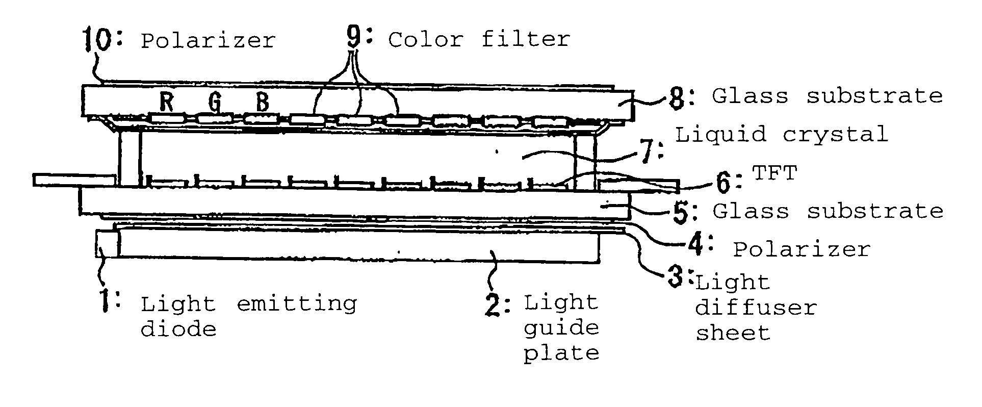
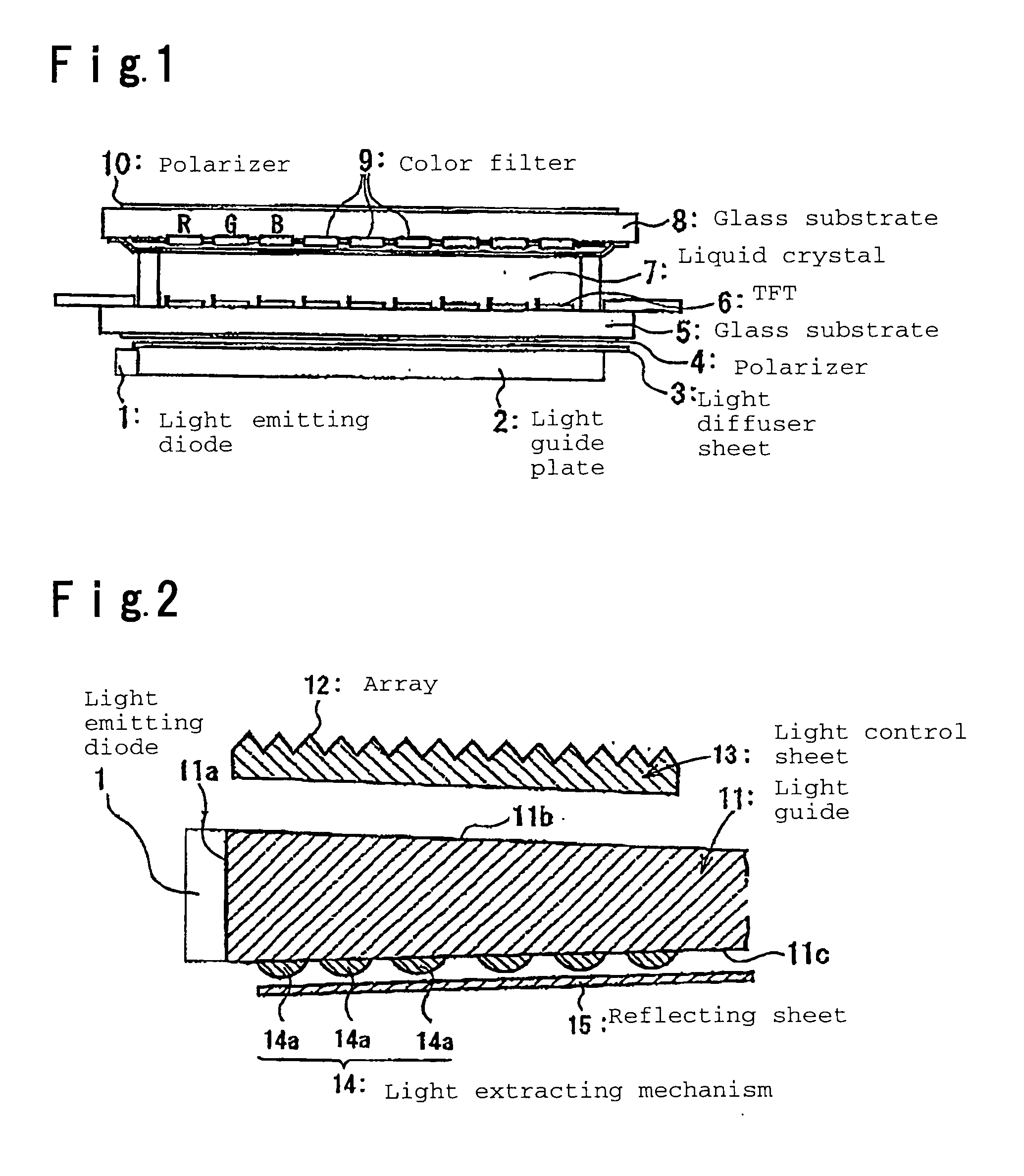
[0232]A light emitting device was prepared in accordance with the following procedure.

[0233]A light emitting diode which emits a light of 460 nm was connected to the bottom of a cup of a frame by die bonding, and then the light emitting diode and an electrode of the frame were connected by wire bonding.

[0234]Ca2.97Ce0.03Sc2Si3O12 as a phosphor which emits light in a green band and Ca0.996Eu0.004S as a phosphor which emits a light in a red band were used. They were kneaded with an epoxy resin to obtain a paste, which was coated on the light emitting diode in the cup and cured.

[0235]Then, a cyclic polyolefin type resin sheet (trade name “ZEONOR” manufactured by Zeon Corporation) of wedge shape, which had a size of 289.6×216.8 mm and thicknesses varying along the direction of a short side between a maximum thickness of 2.0 mm and a minimum thickness of 0.6 mm, was used as a light guide, a light source comprising the above-...

preparation example 2

(1-2) Preparation Example 2

Process of Preparation of Backlight 2

[0240]A backlight 2 was prepared in the same manner as in Preparation Example 1 except that Ca0.992AlSiEu0.008N2.85O0.15 was used as a phosphor which emits a light in a red band. A relative emission spectrum of the backlight 2 thus obtained is presented in FIG. 5.

preparation example 3

(1-3) Preparation Example 3

Process of Preparation of Backlight 3

[0241]A backlight 3 was prepared in the same manner as in Preparation Example 1 except that Ca0.99Ce0.01Sc2O4 was used as a phosphor which emits a light in a green band and Ca0.992AlSiEu0.008N2.85O0.15 was used as a phosphor which emits a light in a red band. A relative emission spectrum of the backlight 3 thus obtained is presented in FIG. 6.


PUM

PropertyMeasurementUnit
wavelengthaaaaaaaaaa

Abstract

The present invention relates to color image display devices having a combination of light shutters, a color filter having color elements of at least three colors of red, green and blue corresponding to the light shutters, and a backlight for transmission illumination, where the backlight has a phosphor layer or a phosphor film, and the phosphor layer or the phosphor film has a compound having at least element M4, element A, element D, element E and element X, where M4 is at least one element selected from Mn, Ce, Pr, Nd, Sm, Eu, Tb, Dy, Ho, Er, Tm and Yb, and includes at least Eu, A is at least one element selected from bivalent metal elements other than the element M4, D is at least one element selected from tetravalent metal elements, E is at least one element selected from trivalent metal elements, and X is at least one element selected from O, N and F.

Description

TECHNICAL FIELD[0001]The present invention relates to a blue composition for a color filter, a color filter and a color image display device. Particularly, it relates to a blue composition for a color filter to realize an image having a high color purity corresponding to the emission wavelength of an improved LED backlight, a color filter and a color image display device.BACKGROUND ART[0002]In recent years, liquid crystal display elements are expected not only in the conventional application to personal computer monitors but also in application to ordinary color televisions. The color gamut of color liquid crystal display elements is determined by chromaticity of light emitted from red, green and blue pixels and, where chromaticity points of the respective color pixels in CIE system of color representation are represented by (xR, yR), (xG, yG), (xB, xB), the color gamut is defined by an area of a triangle surrounded by these three points on a x-y chromaticity diagram. Namely, the la...

Claims


Application Information

Patent Timeline
Patent Type & Authority Applications(United States)
IPC IPC(8): G02F1/13357F21V8/00G02B5/20G02B5/22G02F1/1335
CPCC09B67/0033C09B67/006C09B67/0064C09K11/0883C09K11/7721C09K11/7731G02F1/133621C09K11/7774G02B5/201G02B6/0038G02B6/0053G02F1/133514G02F1/133617C09K11/7734C09K11/77742C09K11/77348G02B5/20C09D17/00
Inventor KAWANA, SHINKANEDA, HIDEAKIKIJIMA, NAOTO
Owner MITSUBISHI CHEM CORP
Why Eureka
Try Eureka