Method for determining the position of an object in a structure

a technology for determining the position of objects and structures, applied in distance measurement, surveying and navigation, instruments, etc., can solve the problems of relatively complicated construction and inaccurate position, and achieve the effect of accurate position determination

Inactive Publication Date: 2010-08-19
KONINKLIJKE PHILIPS ELECTRONICS NV
View PDF9 Cites 67 Cited by
  • Summary
  • Abstract
  • Description
  • Claims
  • Application Information

AI Technical Summary

Benefits of technology

[0005]It is an object of the invention to provide a method for determining the position of an object in a structure that alleviates the above-mentioned drawbacks of the prior art and provides a method for accurate position determination at a reasonably high frequency.
[0011]By measuring phase differences between the modulation signals and a phase reference in order to determine distances to be used in the position determination, the operating frequency involved does not have to be as high as in RF measurements or the above-mentioned propagation time measurement. Still the inventive method provides high position accuracy.
[0013]In accordance with an embodiment of the method, as defined in claim 2, it involves obtaining the comparison phase from a reference signal, which is synchronized with the modulation signals. The synchronization provides for a relatively simple determination of the phase difference, as will be readily understood by a skilled person.
[0019]In accordance with an embodiment of the method, as defined in claim 7, several 3D positions are determined by means of different combinations of modulated light waves, and these several 3D positions are used for optimizing the estimated 3D position. This provides for an additionally increased accuracy.

Problems solved by technology

Relying on the received signal strength, which is attenuated over distance, gives a rather inaccurate position and necessitates additional knowledge about the transmitted signal strength as well.
This alternative solution also uses receive signal strength (RSS) to determine the distance to the light source, and has a relatively complicated construction.
This solution has the drawbacks of requiring a fully synchronized system and very high frequency measurements in order to detect the propagation time and convert that time into a distance with good accuracy.

Method used


Image

  • Method for determining the position of an object in a structure
  • Method for determining the position of an object in a structure
  • Method for determining the position of an object in a structure

Examples


first embodiment

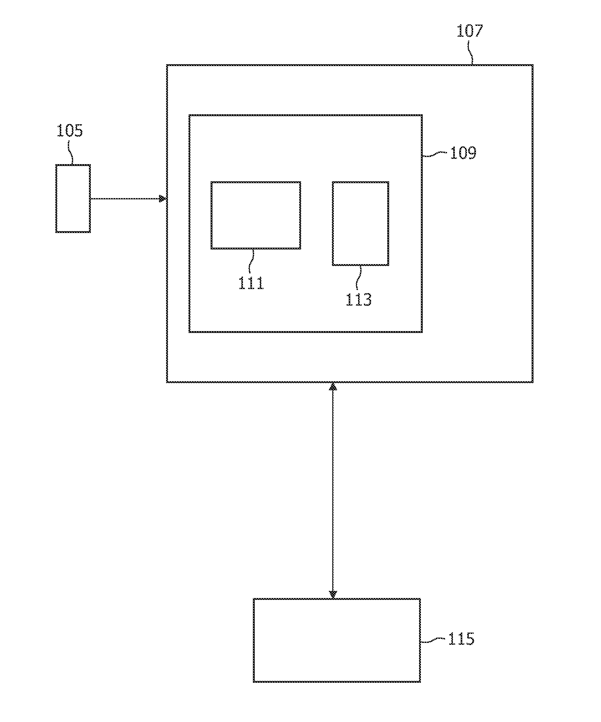
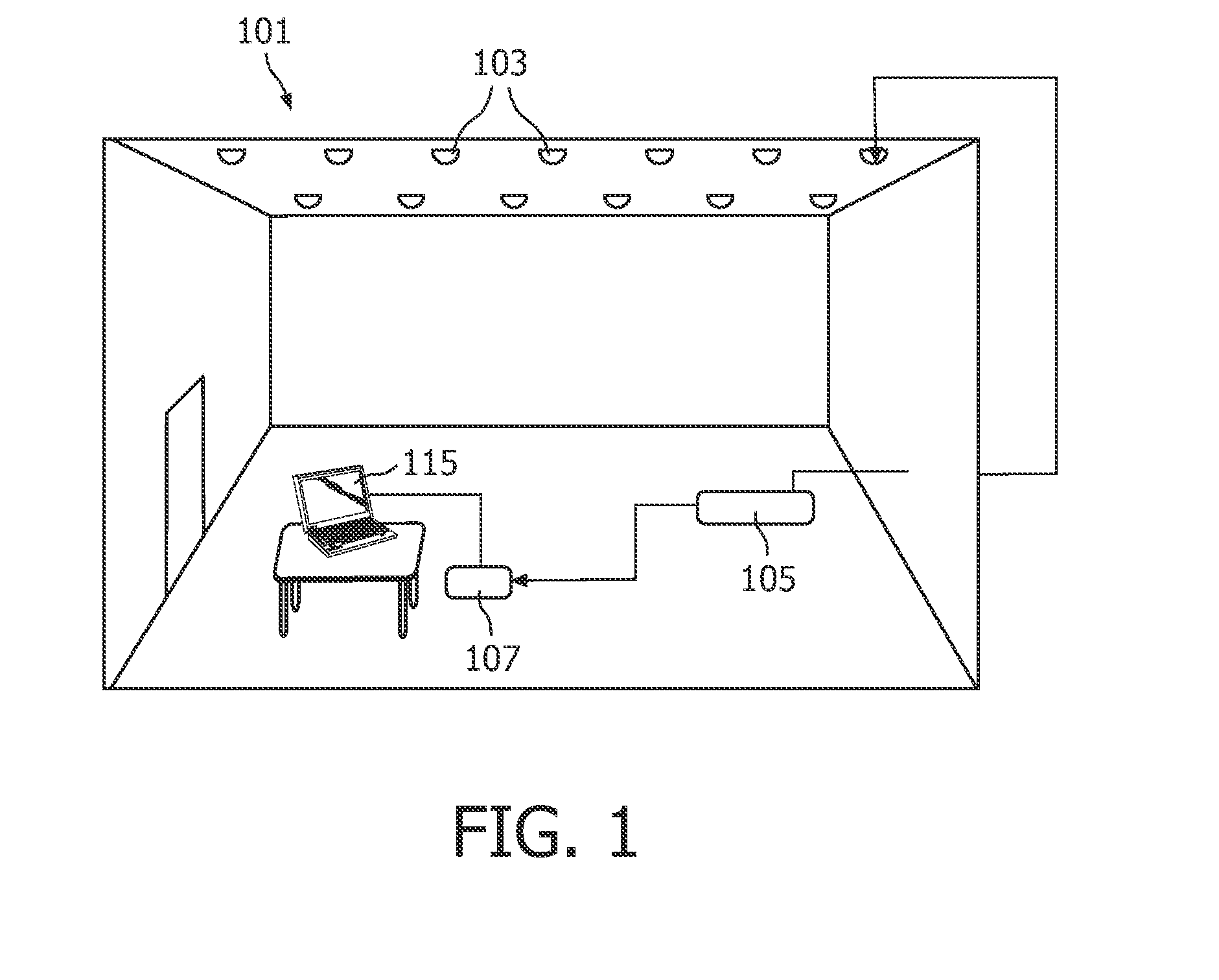
[0025]the method for determining the position of an object in a structure, as shown in FIG. 1, is applicable to a structure 101 where several light sources 103 are arranged, for example in the ceiling (or wall) of a room. An object 107 is in the structure 101. An embodiment of a position determination apparatus 109 provided in the object 107 comprises, as illustrated in FIG. 4, a light detector 111, such as for example a photodiode, and a processor 113, such as a DSP or a CPU. The light sources 103, which could typically be LEDs, are synchronized by a reference clock signal, or simply reference clock, generated by a reference clock signal generator 105. Further, the light detector 111 is also synchronized by the reference clock. The synchronization can be made in any appropriate way as known to a person skilled in the art, wherein the reference signal generator 105 can be a separate device arranged in the structure 101 or be a virtual device representing a common reference clock. Th...

second embodiment

[0029]In the method, the light sources 103 are not synchronized with the light detector 111, but are still mutually synchronized. Then it is a bit more complicated to determine an accurate position. Let us still assume that a 3D position is to be achieved. The light emitted from at least four light sources 103 is needed. By measuring the phase differences between two code signals, the difference in length between the corresponding light sources and the detector 111 is calculated. By calculating at least three such phase differences, i.e. between said at least four light sources 103, it is possible to solving an equation system which gives the distances between the object 107 and the light sources, whereby the 3D position of the object is determined like above.

third embodiment

[0030]However, to obtain a more accurate result, the following steps are performed. First all individual code signals in the detected light are identified, at step 301 (FIG. 3). A 2D matrix is then arranged of all possible pairs of code signals, at step 302. At step 303, the phase difference is calculated for each pair. An arbitrary combination of three phase differences is used for calculating a first 3D position. Using a numerical procedure for calculating the distance from the first 3D position to each one of all other possible positions, results in finding a position with a minimum for the sum of the distances.

[0031]There are several alternative methods to the second embodiment for determining the position when the detector 111 is not synchronized with the light sources 103. Thus, an alternative method is to repeat the steps of the second embodiment above for all possible combinations of 4 light sources 103 and then average the results. Another embodiment includes detecting the...


PUM


Abstract

This invention relates to a method for determining the position of an object in a structure. The object receives modulated light waves from a plurality of light sources, which are arranged in the structure. The modulation is individually coded, and the position of the light sources in the structure is known. The modulation signals are synchronized, and thereby it is possible to determine the position of the object on basis of measuring the phase difference between the phase of each received modulated light wave and a comparison phase. The phase difference is used for distance calculations, which in turn give the position of the object.

Description

FIELD OF THE INVENTION[0001]The present invention relates to a method for determining the position of an object in a structure, which comprises a plurality of light sources emitting modulated light waves modulated by individually coded modulation signals, wherein the position of each light source in the structure is known. The method includes synchronizing the modulation signals, and receiving, at the object, a respective modulated light wave from at least several of said light sources.BACKGROUND OF THE INVENTION[0002]It is widely recognized that controllable light sources, by means of which customized lighting environments can be created, are destined to become the main source of illumination for indoor and outdoor lighting applications. In order to obtain a good controllability the light sources are provided with individual identifiers, in the form of a modulation signal coding the light sources individually. That is, the light emitted from the light sources is coded. Normally the...

Claims


Application Information

Patent Timeline
Patent Type & Authority Applications(United States)
IPC IPC(8): G01C3/08
CPCG01S11/12G01S5/16
Inventor DAMINK, PAULUS HENRICUS ANTONIUSCOLAK, SEL BRIANFERI, LORENZOPENNING DE VRIES, HENDRICUS THEODORUS GERARDUS MARIAMEIJER, EDUARD JOHANNES
Owner KONINKLIJKE PHILIPS ELECTRONICS NV
Why Eureka
Try Eureka