Fluidic lens with reduced optical aberration

a technology of fluidic lenses and optical aberration, which is applied in the field of fluidic lens systems, can solve the problems of inconvenient form-factor of the whole system, difficulty in providing sufficient refractive index difference between the two liquids to provide adequate light-ray bending ability, and system disadvantage of remote location of pressurized fluid sources

Active Publication Date: 2010-08-19
HOLOCHIP
View PDF11 Cites 85 Cited by
  • Summary
  • Abstract
  • Description
  • Claims
  • Application Information

AI Technical Summary

Benefits of technology

[0017]Thus, there is a need in the art, for a fluidic lens that overcomes the above disadvantages.

Problems solved by technology

Although this yields a conveniently compact system, it is difficult to provide enough refractive index difference between the two liquids to provide adequate light-ray bending ability.
Although improved, that system still suffers from the disadvantage that the pressurized fluid source is located remotely.
This makes the form-factor of the whole system inconvenient.
However, while many of the properties of PDMS and similar elastomers may be desirable in fluidic lenses, the value of the Young's modulus presents an inherent disadvantage for certain applications.
That is, for a lens having a membrane with a sufficiently low modulus, the lens may be susceptible to disturbances, such as instabilities in focus and tilt due to forces of acceleration, and aberrations, such as coma, which may be due to gravitational forces.
However, disadvantages with pre-tensioning the membrane may include a slow long-term relaxation of the membrane that lowers its effective stiffness, sensitivity to small non-uniformities in tension of the membrane resulting in optical aberrations across the dynamic range of the lens, and the possible appearance of bulk defects in the membrane upon tensioning that result in optical scattering.
Another inherent disadvantage of PDMS is its permeability, or inability to effectively block the passage of some gases and fluids.
Such permeability may result in air bubbles developing in, or fluid leaking out of, the lens.
These effects can diminish the durability, lifetime, optical quality, dynamic range and other performance properties of the lens.
However, these approaches can result in disadvantageous effects such as increasing the complexity of fabrication, optical scatter and loss, and aberrations.

Method used


Image

  • Fluidic lens with reduced optical aberration
  • Fluidic lens with reduced optical aberration
  • Fluidic lens with reduced optical aberration

Examples


Embodiment Construction

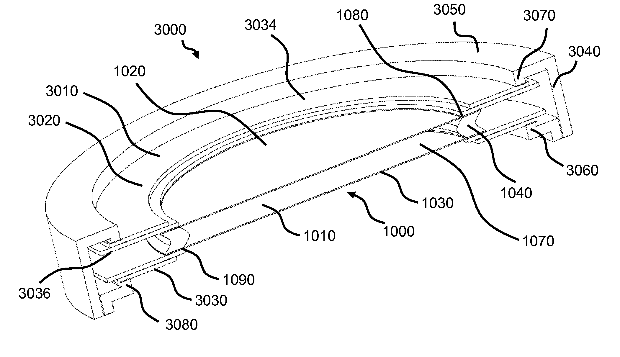
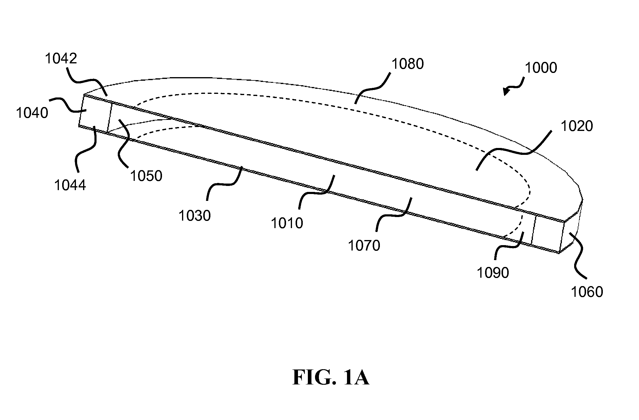
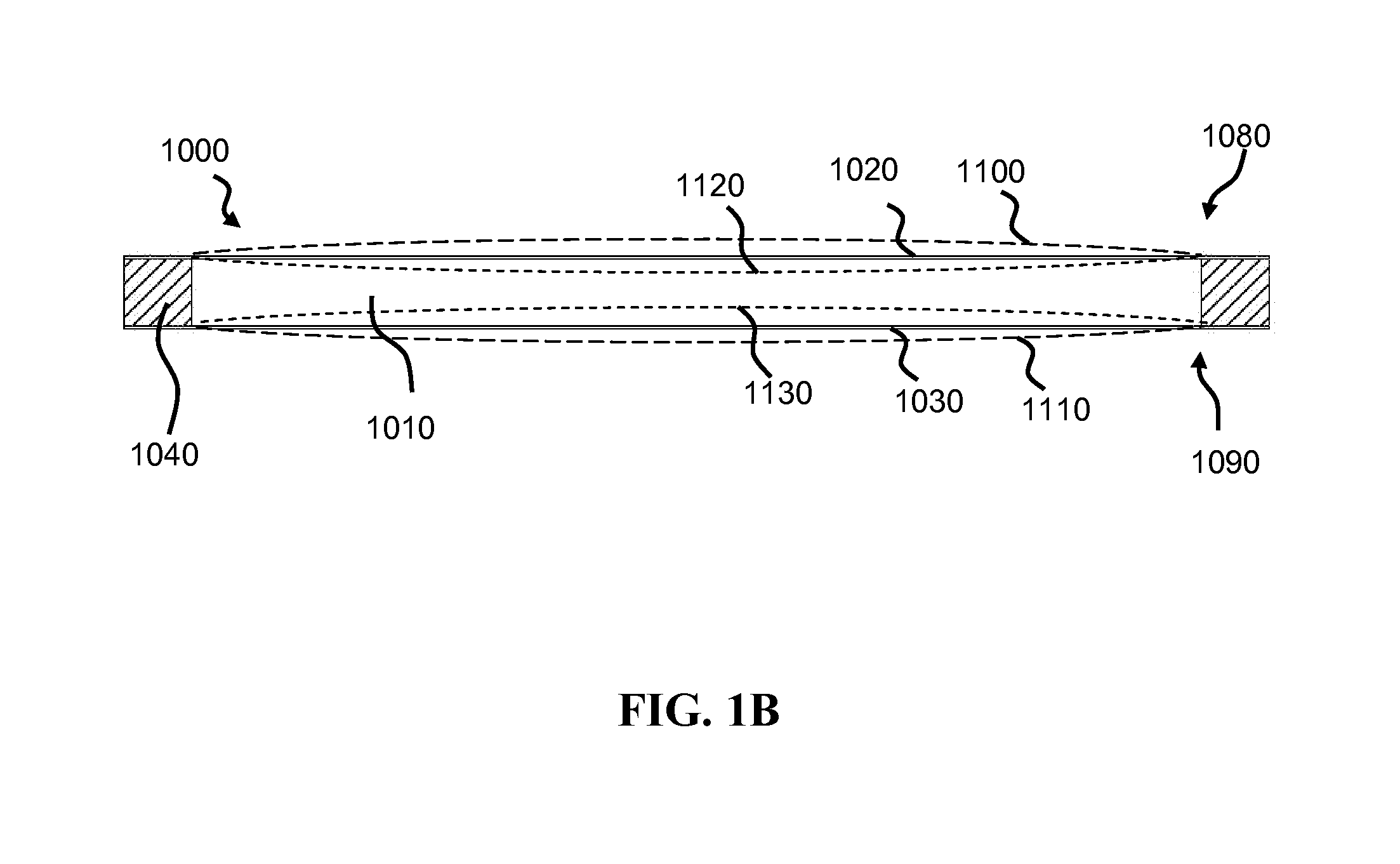
[0080]FIG. 1A shows a lens member 1000 according to an embodiment of the present invention. A lens chamber 1010 is defined by a first optical surface 1020 and a second optical surface 1030 (also referred to as “optical surfaces 1020, 1030”). Optical surfaces 1020, 1030 may include rigid and / or compliant materials, including elastic membranes, elastic members, elastic thick optical elements and static optical elements. In the present embodiment, optical surfaces 1020, 1030 may include elastic and / or resilient, low elastic modulus, high elastic modulus, low stiffness, or high stiffness membrane material such as elastomer, plastic, semiconductor, crystal, metal, thick glass and thin glass sheets. Further, any of these materials may be pre-tensioned or not pre-tensioned. In the present embodiment, optical surfaces 1020, 1030 may be disposed generally parallel and at a given distance apart (or “separation” or “gap”) from each other when lens member 1000 is in a first state of actuation; ...


PUM


Abstract

A fluidic lens device capable of providing variable focal power with reduced optical aberration is disclosed. The device includes a lens member and an actuator. The lens member comprises one or more elastic optical surfaces, a compliant support member in communication with the optical surfaces, and a fluid-filled chamber. The optical surfaces have a high value of elastic modulus, reducing coma and other aberrations associated gravity and acceleration. The support member may provide a compliant fluid seal and allow the edges of the optical surfaces to pivot, reducing spherical and other aberrations. One or more piezoelectric ring-bender actuators may provide the force required for compressing the support ring and deflecting the optical surfaces. The actuators may be configured to provide the fluidic lens device with reduced sensitivity to changes in temperature.

Description

CLAIM OF PRIORITY[0001]This application is related to and claims the priority benefit of commonly-assigned U.S. Provisional Patent Application No. 61 / 171,044, to Robert G. Batchko et al., entitled “VARIABLE-FOCAL-LENGTH FLUIDIC LENS WITH REDUCED OPTICAL ABERRATION” (Attorney Docket No. HCP-007 / PROV), filed Apr. 20, 2009 the entire disclosures of which are incorporated herein by reference in its entirety.[0002]This application claims the benefit of priority of the U.S. Provisional Patent Application No. 60 / 747,181, entitled “ELECTROSTATIC ACTUATION OF FLUIDIC LENS”, filed May 12, 2006, which is hereby incorporated by reference. This application is a continuation-in-part of commonly assigned U.S. patent application Ser. No. 11 / 383,216 entitled “FLUIDIC OPTICAL DEVICE”, and published as US Patent Application Publication Number 20070030573, the contents of which are incorporated herein by reference. This application claims the benefit of priority of U.S. patent application Ser. No. 11 / 3...

Claims


Application Information

Patent Timeline
Patent Type & Authority Applications(United States)
IPC IPC(8): G02B3/14
CPCG02B3/14G02B26/005G02B5/20B33Y80/00F03G7/065
Inventor BATCHKO, ROBERT G.SZILAGYI, ANDREI
Owner HOLOCHIP
Why Eureka
Try Eureka