Multi-layer woven fabric display

a multi-layer, textile technology, applied in the field of textiles, can solve the problems of color display of textiles, short circuits, etc., and achieve the effects of reducing the risk of short circuit, preventing electrically conductive yarns, and facilitating the connection of electronic components

Inactive Publication Date: 2010-08-19
KONINKLIJKE PHILIPS ELECTRONICS NV
View PDF7 Cites 49 Cited by
  • Summary
  • Abstract
  • Description
  • Claims
  • Application Information

AI Technical Summary

Benefits of technology

[0011]An advantage of the present invention is that the risk for short circuit is reduced when e.g. bending, buckling, folding or wrinkling the textile since the electrically conductive warp yarns of the first layer are partially covered by the insulating weft yarns. The zones where insulating weft yarns do not cover the conductive yarns of the warp or where no insulating warp yarn covers the conductive weft yarns may be used for connection of electronic components, thereby resulting in a completely electrically isolated surface after assembly of the components.
[0012]The interweaving of the electrically insulating yarns provides insulating floats at the first face of the textile, thereby preventing electrically conductive yarns of the first layer from short-circuiting.
[0013]Another advantage of the present invention is that the textile facilitates the connection of electronic components as the conductive yarns are non insulated, i.e. there is no need of removing an outer layer of the yarn before the connection of a component.
[0014]Another advantage of the present invention is that the creation or realization of crossover points or via connections from one face of the textile to another is facilitated as an electrical contact between a conductive yarn of the warp and a conductive yarn of the w

Problems solved by technology

However, as the conductive yarns are not insulated, short-circuits may occur, e.g. when folding or wrinkling the fabric.
A short-circuit between addressing lines of the fabric may modify the color displayed by the textile, which is undesirable.
However, this alternative results in a need of removal of the outer insulating l

Method used


Image

  • Multi-layer woven fabric display
  • Multi-layer woven fabric display
  • Multi-layer woven fabric display

Examples


Embodiment Construction

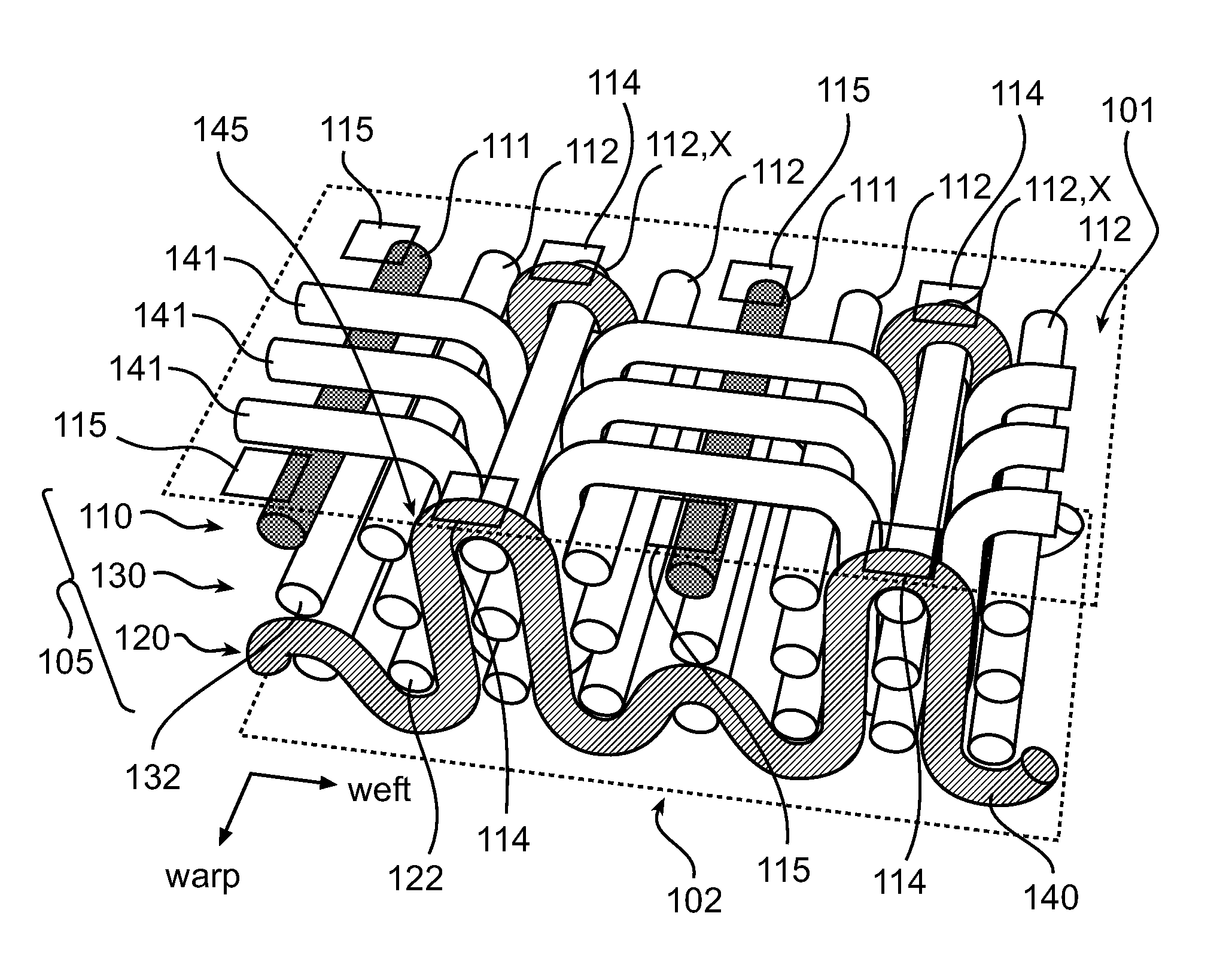
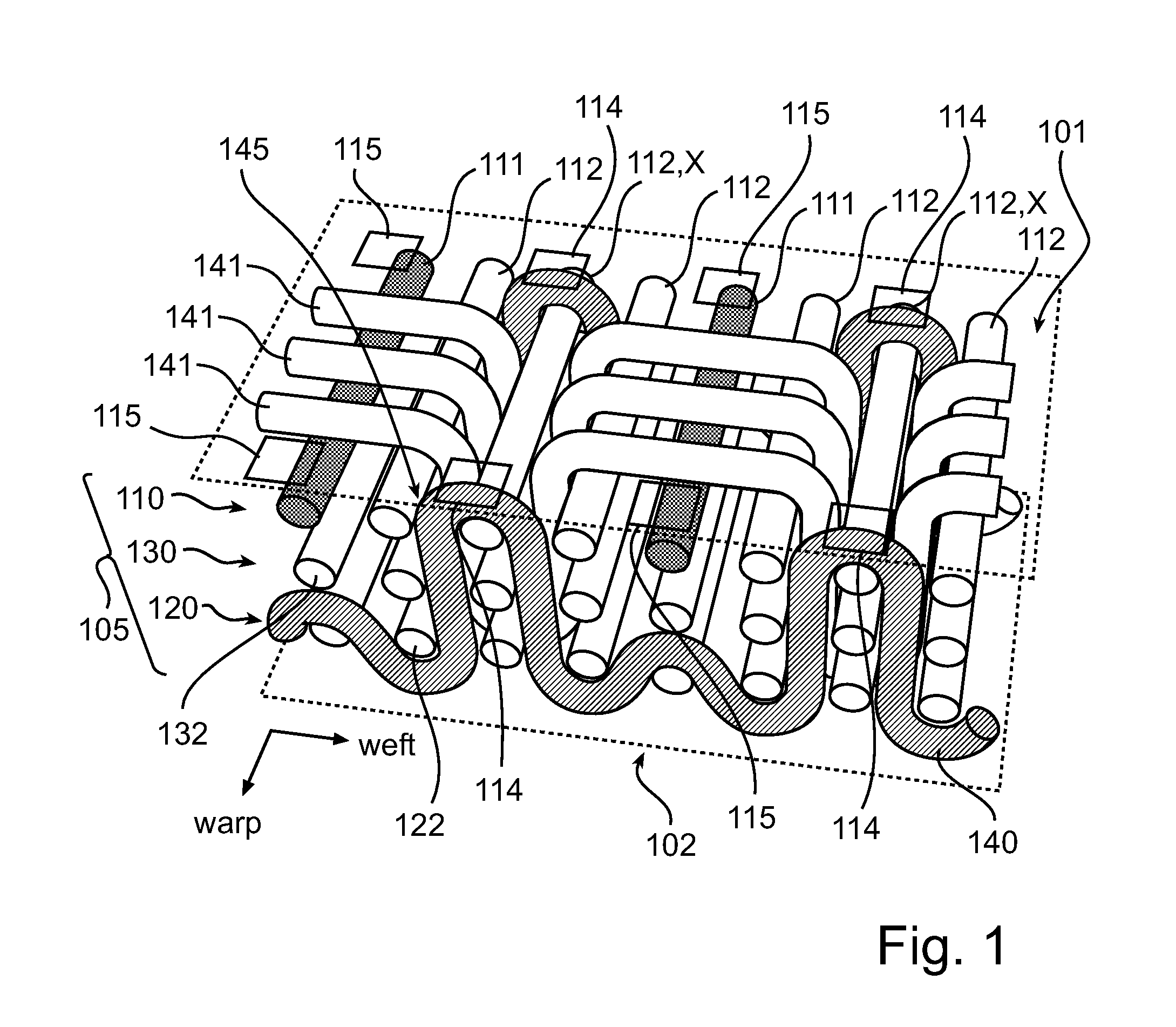
[0031]With reference to FIG. 1, a first embodiment of the present invention will be described.

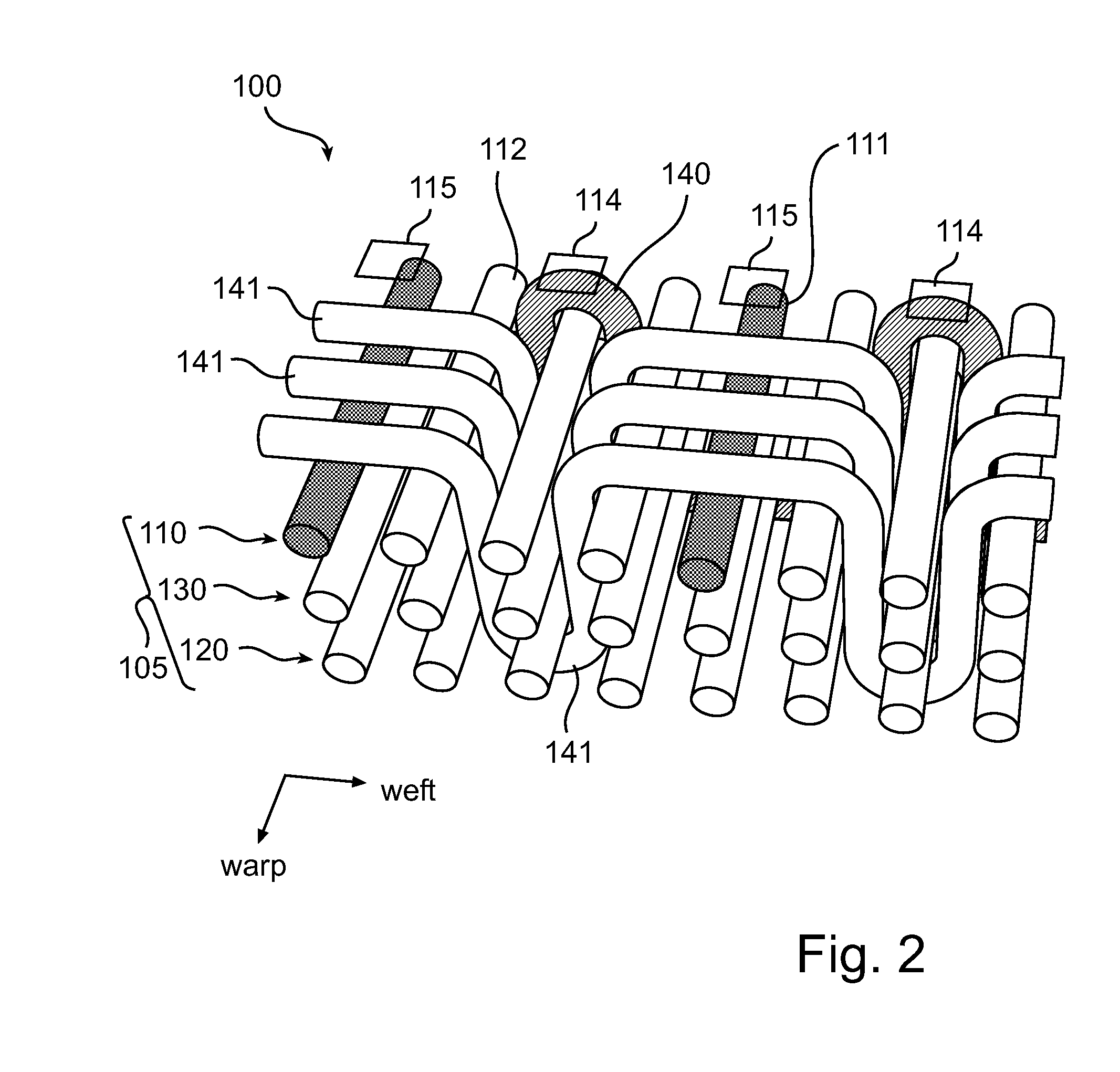
[0032]FIG. 1 shows a cross-sectional view of a textile 100 illustrating the weaving of an electrically conductive weft yarn 140 in a multilayer warp 105. The multilayer warp 105 of the textile (or fabric) 100 comprises a first layer 110, a second layer 120 and a third layer 130 arranged between the first layer 110 and the second layer 120. The yarns 111 and 112 of the first, second and third layers 110, 120 and 130 are arranged along a so-called warp direction, thereby defining the multilayer warp 105. The first layer 110 comprises electrically conductive yarns 111 electrically isolated from each other by at least one electrically insulating yarn 112. In the present embodiment, two adjacent electrically conductive warp yarns 111 of the first layer 110 are electrically separated by three electrically insulating warp yarns 112. The second and third layers 120 and 130 comprise electrically ins...


PUM

PropertyMeasurementUnit
Electrical conductivityaaaaaaaaaa
Structureaaaaaaaaaa
Flexibilityaaaaaaaaaa

Abstract

The present invention relates to textiles for photonic and electronic applications, particularly to multilayer textiles made of electrically conductive yarns for driving electrical components such as light emitting diodes connected to the textile. The light emitting diodes may be arranged in the form of an array in order to realize a flexible and foldable display. In the textile according to the present invention, insulating weft yarns are interwoven in a multilayer wrap (105) such that the electrically warp yarns (111) are partially covered by the insulating weft yarns (141), thereby preventing from short-circuit between electrically conductive yarns of the textile. In particular, the structure of the textile according to the present invention may be satin/sateen weave structure.

Description

FIELD OF THE INVENTION[0001]The present invention relates to textiles for photonic and electronic applications. In particular, the present invention relates to multilayer textiles made of electrically conductive yarns for driving electrical components such as light emitting diodes connected to the textile.BACKGROUND OF THE INVENTION[0002]Many types of textiles are already in use in our every day life, and new application fields for these textiles have emerged as electronics is now integrated into these textiles. For instance, photonic textiles such as fabrics comprising light emitting diodes (LED) open up a wide range of new interior and apparel applications, ranging from illumination to atmosphere creation to messaging. Very compact, low-power LED packages, available as so-called surface mounted devices, can be attached to the textile by e.g. gluing, snap button connection or stitching. This advantageously provides new types of e.g. foldable and flexible displays.[0003]The fabric s...

Claims


Application Information

Patent Timeline
IPC IPC(8): H05K1/03D03D11/00
CPCD03D1/0088D03D11/00D10B2401/16H05K2201/0281H05K2201/029H05K2201/10106H05K1/189H05K1/038Y10T442/3203D03D15/00D03D23/00
Inventor ASVADI, SIMAVAN PIETERSON, LIESBETH
Owner KONINKLIJKE PHILIPS ELECTRONICS NV
Why Eureka
Try Eureka