
Closure device for lines for administering medical or pharmaceutical fluids from containers or the like

a technology for closing devices and containers, applied in liquid bottling, flow monitors, packaging under special atmospheric conditions, etc., can solve the problems of limited mechanical resistance to wear and break, intoxication or irritation, and short-term loss of efficiency of known closure devices, etc., to increase the mechanical resistance and efficiency of temporary locking

Inactive Publication Date: 2010-08-19
ARIES
View PDF7 Cites 34 Cited by
  • Summary
  • Abstract
  • Description
  • Claims
  • Application Information

AI Technical Summary

Benefits of technology

[0013]The aim of the present invention is to eliminate the drawbacks cited above of the background art, by providing a closure device for lines for administering medical or pharmaceutical fluids from containers, particularly syringes, bags, catheters, tubes and the like, which allows to increase the mechanical resistance and efficiency of the temporary locking means.
[0014]Within this aim, an object of the invention is to reduce the mutual rotation stroke between the tubular bodies, improving the mating efficiency of the pins with the respective receptacles.
[0015]Another object of the invention is to protect the mutually moving elements, in particular the two tubular bodies, against agents which are external to said closure device.
[0016]Another object of the present invention is to provide a closure device which is simple, relatively easy to provide in practice, safe in use, effective in operation, and has a relatively low cost.

Problems solved by technology

It is necessary to avoid accidental leaks or losses of the medical or pharmaceutical fluids during the steps for their preparation, transport and administration, since such leaks might cause intoxications or irritations to anyone coming into contact with them.
These known types of closure device are in any case not free from drawbacks, including the fact that the wings for locking temporarily the relative axial translational stroke of the two bodies have, in some operating conditions, limited mechanical resistance to wear and break and / or lose efficiency in the short term.
Further, it has been observed in known types of device that the pins associated with one of the tubular bodies, if subjected to vigorous rotation by the specialized user, can bend, for example in a radial direction, the wings for their retention, thus thwarting their locking action.

Method used


Image

  • Closure device for lines for administering medical or pharmaceutical fluids from containers or the like
  • Closure device for lines for administering medical or pharmaceutical fluids from containers or the like
  • Closure device for lines for administering medical or pharmaceutical fluids from containers or the like

Examples


first embodiment

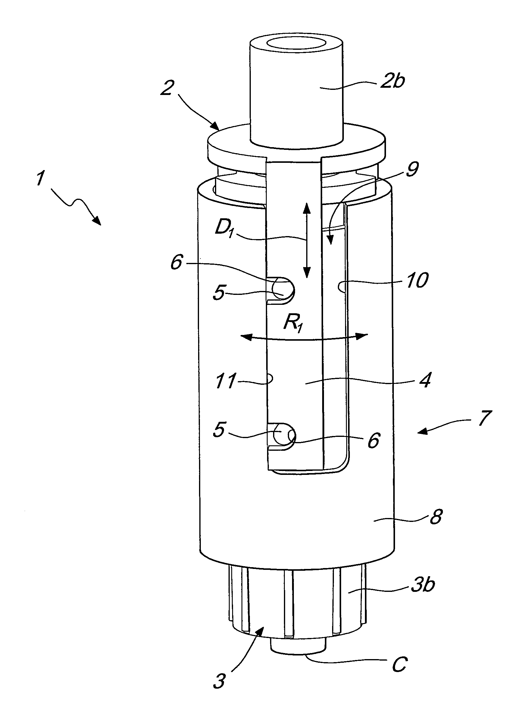
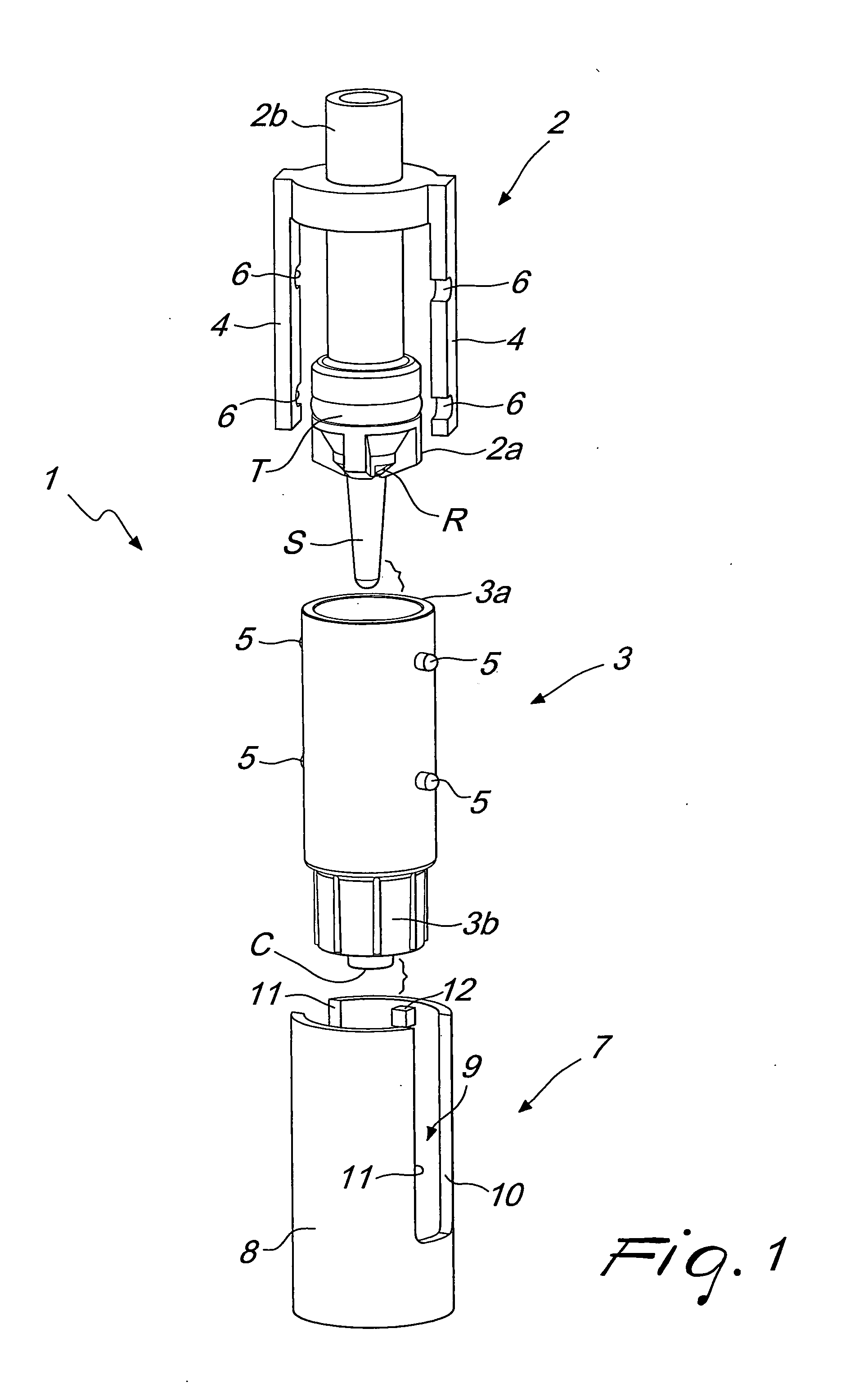
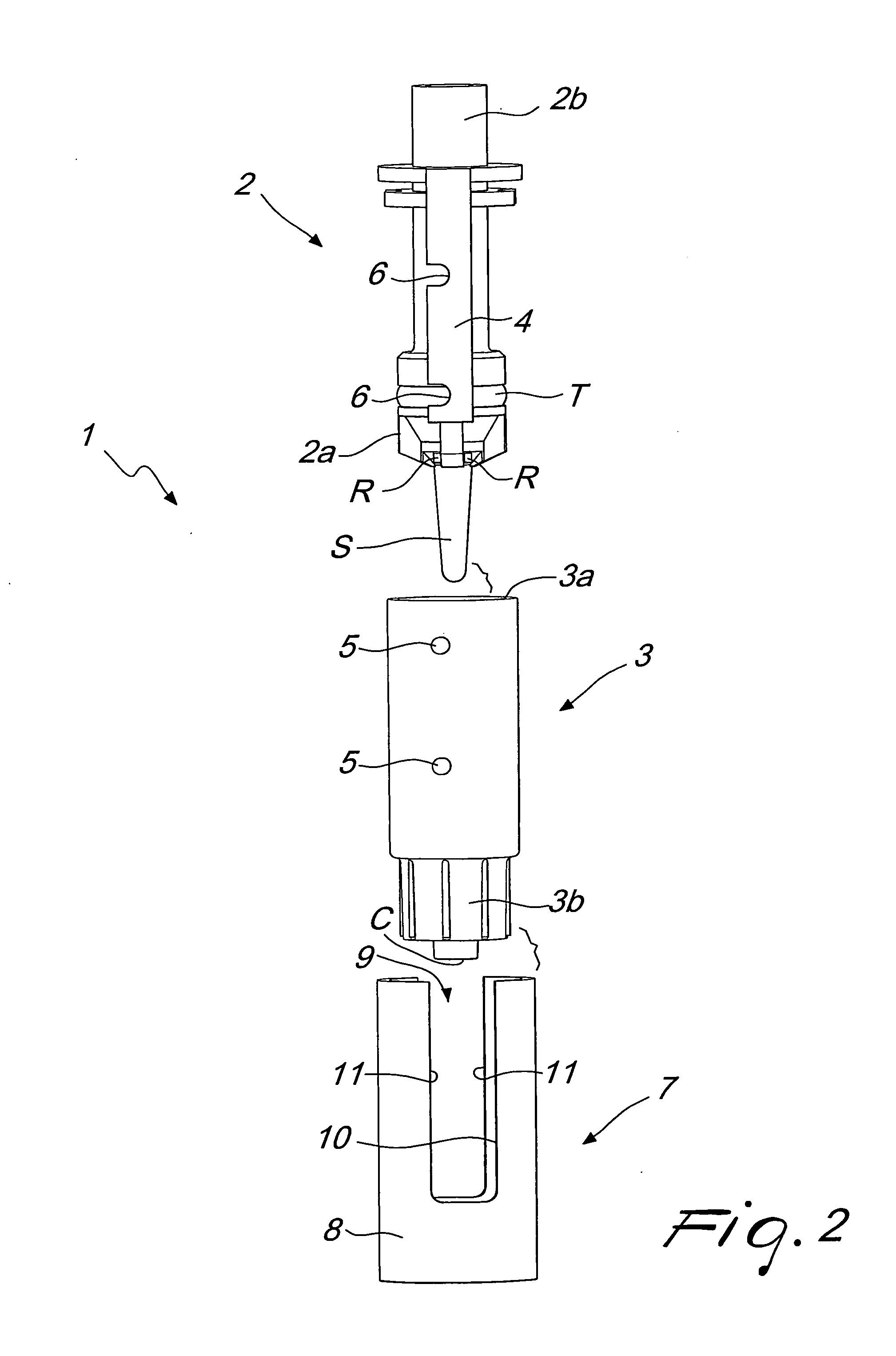
[0045]In a first embodiment, shown in FIGS. 1 to 5, advantageously the temporary locking means comprise at least one wing 4, which protrudes from the first tubular body 2 and is substantially parallel to the axis of said first tubular body.

[0046]The wing 4 can be superimposed on the outer surface of the second tubular body 3.

[0047]The temporary locking means comprise at least one pin 5, which is associated with at least one of the first tubular body 2 and the second tubular body 3 and is adapted to engage in at least one receptacle 6 which is associated with the other of said first and second tubular bodies.

[0048]The locking means comprise at least one pair of receptacles 6 for temporarily retaining said pin respectively in the open configuration and in the closed configuration.

[0049]The pin 5 protrudes from said outer surface of the second tubular body 3 for insertion in the at least one receptacle 6 of the pin 5 provided on the wing 4.

[0050]In particular, the temporary locking mea...

second embodiment

[0075]In a second embodiment, shown in FIGS. 6 to 9 and studied in order to reduce the number of components that form the device 1, the locking means are formed monolithically with the first tubular body 2 and with the second tubular body 3.

[0076]In this case also, the temporary locking means comprise at least one pin 5 which is associated with at least one of the first and second tubular bodies 2 and 3 and is adapted to engage in at least one receptacle 6 which is associated with the other of said first and second tubular bodies and further comprise at least one pair of receptacles 6 for temporarily retaining said pin respectively in the open configuration and in the closed configuration.

[0077]In particular, the second tubular body 3 comprises a tubular portion 3′, which is coupled inside the second tubular body 3 and is rigidly associable therewith, for example by means of interlocking couplings or other technically equivalent solutions.

[0078]In turn, the tubular portion 3′ can be...


PUM

PropertyMeasurementUnit
relative rotationaaaaaaaaaa
direction of mutual rotationaaaaaaaaaa
widthaaaaaaaaaa

Abstract

A device for closing lines for administering medical or pharmaceutical fluids from containers and the like, comprising: a first tubular body and a second tubular body, which are mutually associated and able to move axially by sliding and / or rotating with respect to each other; a valve element for adjusting the flow of the fluid formed inside the first and second tubular bodies, the relative movement of the first and second tubular bodies being adapted to move the valve element from a closed configuration for blocking the flow of the fluid to an open configuration for feeding the fluid; elements for limiting the relative rotation between the first and second tubular bodies which are monolithically connected to at least one of the first and second tubular bodies.

Description

[0001]The present invention relates to a closure device for lines for administering medical or pharmaceutical fluids from containers and the like, particularly syringes, bags, catheters, tubes and the like.BACKGROUND OF THE INVENTION[0002]In particular, the device according to the invention is used in medical fields in which the medical or pharmaceutical fluids have a high degree of toxicity or irritancy, for example chemotherapy fluids, or other drugs used to treat oncologic disorders.[0003]The individual doses of such drugs to be administered to the patient are generally prepared by specialized medical staff of the medical facility. In particular, the drugs are packaged in containers, for example bags or bottles, from which specialized staff, with the aid of conventional syringes, draws the individual doses to be administered to the patient by means of suitable administration devices, such as for example phleboclyses, catheters or the like.[0004]It is necessary to avoid accidental...

Claims


Application Information

Patent Timeline
Patent Type & Authority Applications(United States)
IPC IPC(8): A61M39/22B67C3/20
CPCA61J1/1437A61M5/16881A61M39/10A61M2039/1027A61M39/1055A61M39/22A61M39/1011
Inventor GRECO, FRANCESCO
Owner ARIES
Learn More