Assembly and Method for Introducing a Reducing Agent into the Exhaust Pipe of an Exhaust System of an Internal Combustion Engine

a technology of exhaust system and reducing agent, which is applied in the direction of machines/engines, mechanical equipment, membrane technology, etc., can solve the problem of complete blockage of the exhaust pip

Inactive Publication Date: 2010-08-26
FAURECIA EMISSIONS CONTROL TECH GERMANY
View PDF11 Cites 120 Cited by
  • Summary
  • Abstract
  • Description
  • Claims
  • Application Information

AI Technical Summary

Benefits of technology

[0006]An assembly includes a feed connector which opens into an exhaust pipe and has a wall, a feed device for reducing agents which opens into the feed connector, and a device that generates a gas flow which is additional to the reducing agent flow and lines the wall of the feed connector. This additional gas flow (which is also different from a main exhaust gas flow in the exhaust pipe) is at least largely free of reducing agent and prevents any mist produced upon injection of a reducing agent from depositing on the walls of both the feed connector and the exhaust pipe.
[0012]Preferably, the guide member extends from the feed device at least partially along the wall of the feed connector. In the region of the feed device or a mount for the feed device, the guide member more particularly rests directly against the wall. This prevents any reducing agent from reaching an area between the guide member and the wall.
[0018]The device is preferably configured such that the gas flow is formed as a swirl flowing in the feed connector, something which enhances the mixing in the feed connector. This swirling of the gas flow in the feed connector may be attained by a suitably designed and arranged guide member and / or an oblique inlet opening.
[0019]More specifically, the feed connector is arranged at an angle of from 20° to 70° in relation to the exhaust pipe, which results in a particularly favorable distribution of the supplied reducing agent.
[0020]For a better mixing of the supplied reducing agent with the exhaust gas flow, a mixing element that causes a swirling of the exhaust gas flow is advantageously arranged in the exhaust pipe downstream of the feed connector.
[0027]As already discussed above in relation to the corresponding assembly, the reducing agent deposits occurring in the prior art are also effectively prevented by this method.

Problems solved by technology

This is a problem, in particular for low-load, low-temperature operation of the internal combustion engine, in which the deposits are not vaporized again and may eventually completely block the exhaust pipe.

Method used


Image

  • Assembly and Method for Introducing a Reducing Agent into the Exhaust Pipe of an Exhaust System of an Internal Combustion Engine
  • Assembly and Method for Introducing a Reducing Agent into the Exhaust Pipe of an Exhaust System of an Internal Combustion Engine
  • Assembly and Method for Introducing a Reducing Agent into the Exhaust Pipe of an Exhaust System of an Internal Combustion Engine

Examples


Embodiment Construction

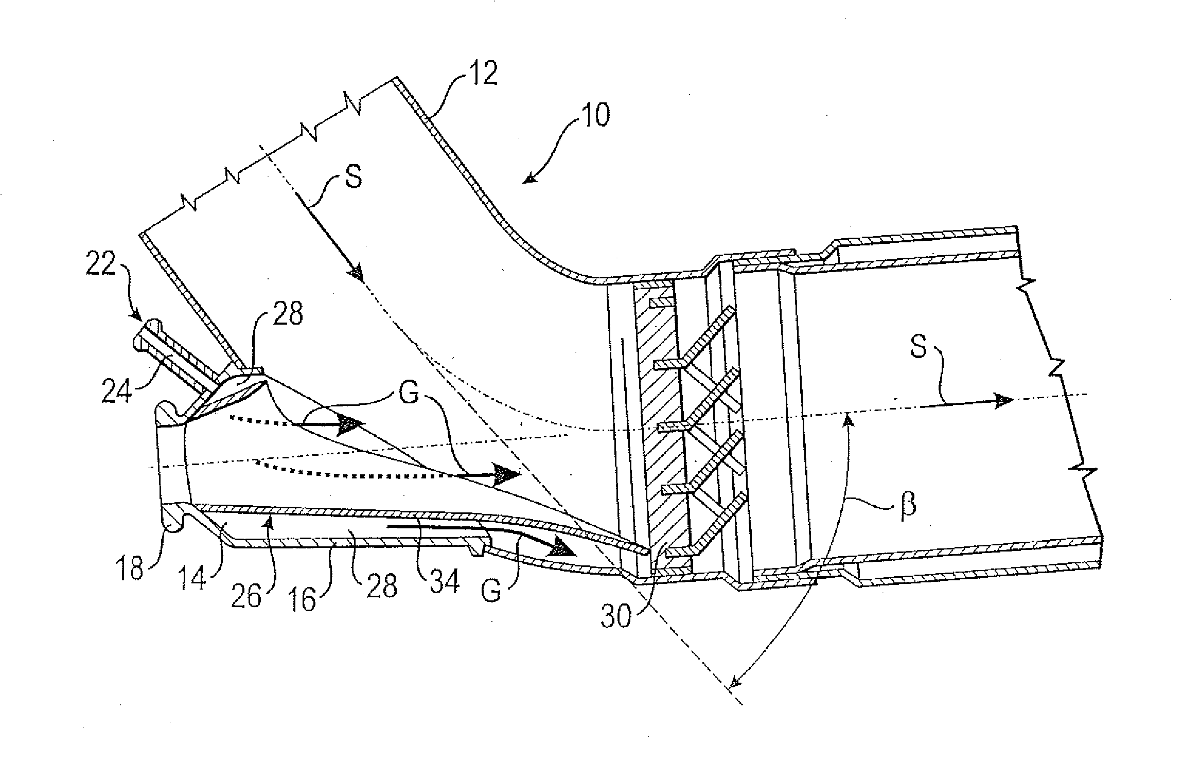
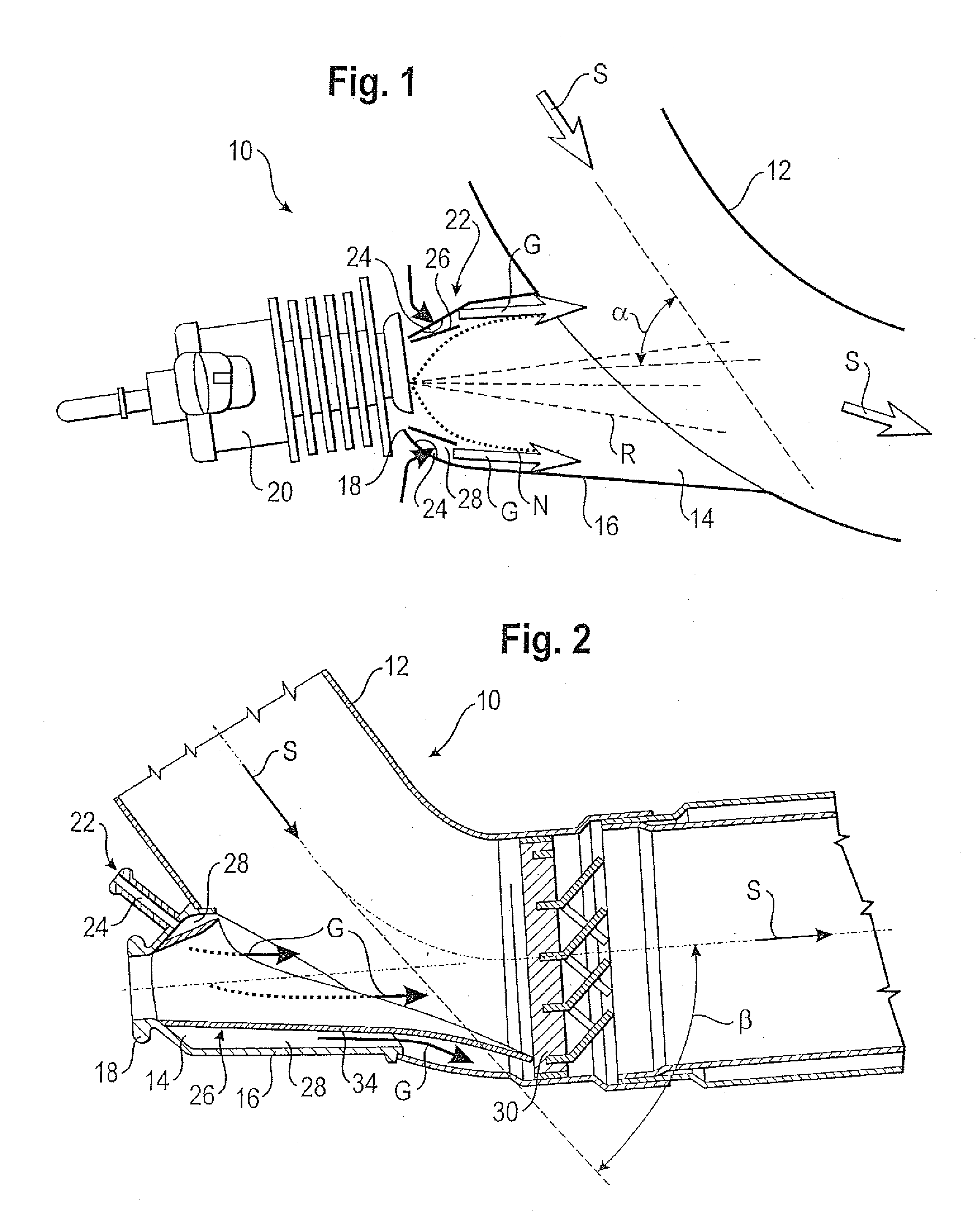
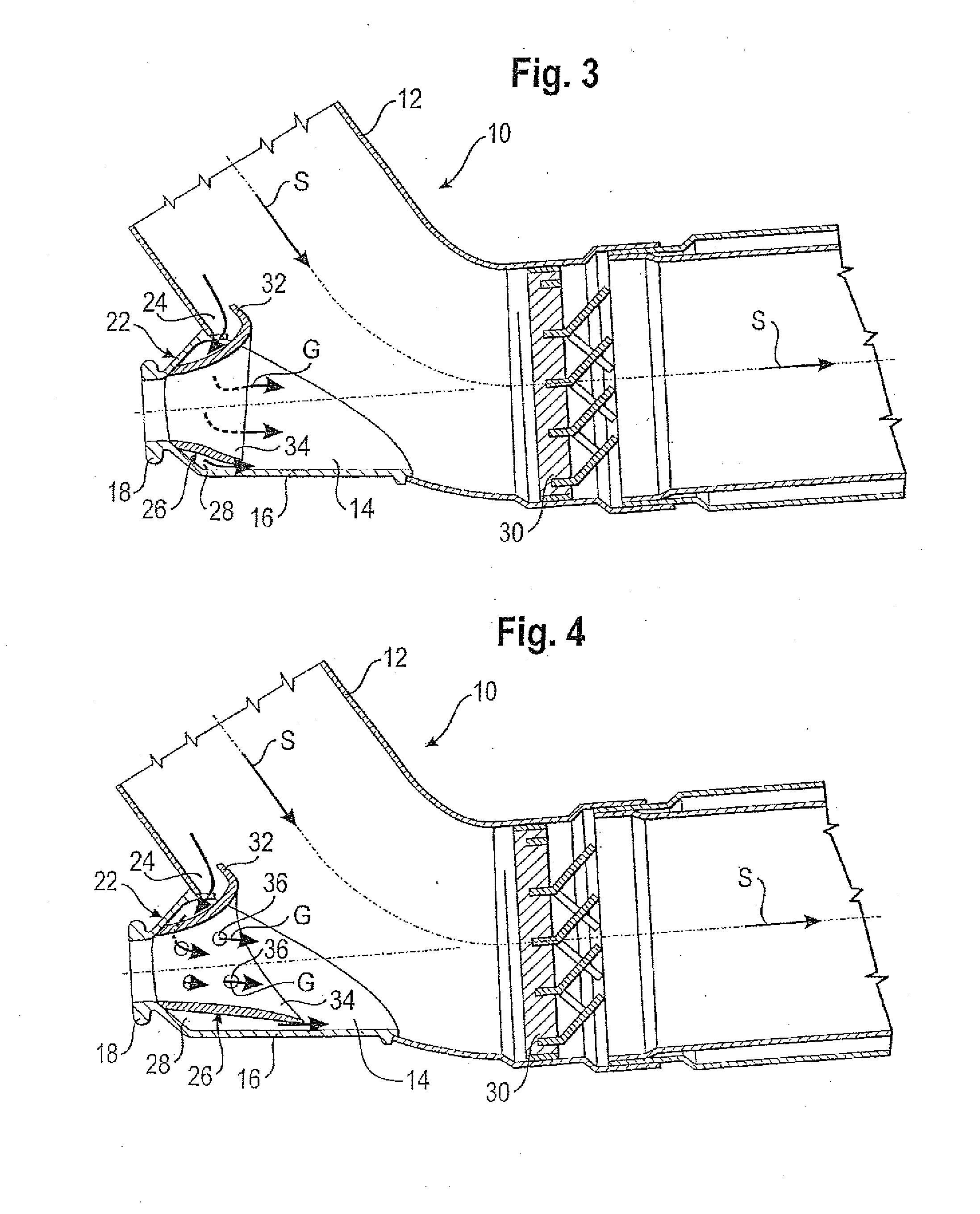
[0038]FIG. 1 schematically shows an assembly 10 that introduces a reducing agent into an exhaust pipe 12 of an exhaust system of an internal combustion engine. In particular, the exhaust system of a motor vehicle is involved. The exhaust gas flow in the exhaust pipe 12 is denoted by S. The assembly 10 includes a feed connector 14 which is of a substantially conical configuration and opens into the exhaust pipe 12, preferably at an angle a of between 20° and 70°, and in the example shown is approximately 55°. An inside wall of the feed connector 14 is identified by reference number 16.

[0039]A feed device 20 for reducing agents is arranged in a mount 18 provided at an end of the feed connector 14 that is opposite to the exhaust pipe 12. The feed device 20 opens into the feed connector 14 and is an injection valve, in this case a low-pressure fuel injection valve. The reducing agent preferably is an aqueous urea solution which is introduced into the exhaust pipe 12 upstream of an SCR c...


PUM

PropertyMeasurementUnit
angleaaaaaaaaaa
angleaaaaaaaaaa
angleaaaaaaaaaa

Abstract

An assembly and method for introducing a reducing agent into an exhaust pipe of an exhaust system of an internal combustion engine, in particular of a motor vehicle includes a feed connector which opens into the exhaust pipe and has a wall; a feed device for reducing agents which opens into the feed connector; and a device that generates a gas flow which is additional to the reducing agent flow and lines the wall of the feed connector.

Description

RELATED APPLICATION[0001]This application is the U.S. national phase application of PCT / EP2008 / 005170, filed 25 Jun. 2008, which claims priority to German Application Serial No. 10 2007 034 316.9, filed 24 Jul. 2007, and German Application Serial No. 20 2008 001 547.2, filed 4 Feb. 2008.BACKGROUND OF THE INVENTION[0002]The present invention relates to an assembly for introducing a reducing agent into the exhaust pipe of an exhaust system of an internal combustion engine, in particular of a motor vehicle. The present invention further relates to a method of introducing a reducing agent into the exhaust pipe of an exhaust system of an internal combustion engine, in particular of a motor vehicle.[0003]To comply with specifications relating to environmental laws, exhaust gases such as those of motor vehicles driven by internal combustion engines need to be subjected to a purification. In particular, for nitrogen oxide reduction, so-called “SCR catalytic converters” (also referred to as ...

Claims


Application Information

Patent Timeline
Patent Type & Authority Applications(United States)
IPC IPC(8): F01N3/20
CPCB01D2251/206B01D2259/12F01N3/2066F01N13/08Y02T10/24F01N2260/022F01N2610/02F01N2610/08F01N2610/1453F01N2240/20Y02A50/20Y02T10/12F01N3/2892B01D2251/2062F01N3/206F01N2470/00
Inventor RUSCH, KLAUSKAISER, ROLFFORSTER, ERICH
Owner FAURECIA EMISSIONS CONTROL TECH GERMANY
Why Eureka
Try Eureka