Dehumidifying Cooling Device for District Heating

a cooling device and district heating technology, applied in the field of district heating, can solve the problems of deterioration in the economic efficiency of cogeneration, uneconomical high water return temperature of absorption chiller, and limit on the improvement of performance, so as to reduce device size, reduce manufacturing costs, and simplify the system configuration

Inactive Publication Date: 2010-08-26
KOREA DISTRICT HEATING CORP
View PDF9 Cites 13 Cited by
  • Summary
  • Abstract
  • Description
  • Claims
  • Application Information

AI Technical Summary

Benefits of technology

[0022]According to a dehumidifying cooling device for district heating of the present invention having the above described configuration, it is possible to provide air cooling by use of hot water supplied by large-scale or small-scale district heating systems and gas or oil boilers installed in individual households. Accordingly, the present invention has the effect of achieving a reduced device size through the implementation of the cooling operation without a compressor, and reduced manufacturing costs by virtue of a simplified system configuration.

Problems solved by technology

As a result, the operation rate of dedicatrd heating in summer decreases to less than 10%, and this causes deterioration in the economic efficiency of cogeneration.
However, in spite of various researches and developments for improving the performance of the absorption chiller, there is a limit on the improvement of performance due to the low temperature of a heating source.
In addition, the absorption chiller has an uneconomical high water return temperature because it cannot use water having a temperature of 80° C. or less, and suffers from a small differential between the temperature of supplied water and the temperature of returned water.
When the absorption chiller is installed in an apartment, etc. taking up the largest portion of district heating to provide central cooling, there is a problem in that cold water pipes have to be additionally installed regardless of hot water supply pipes.

Method used


Image

  • Dehumidifying Cooling Device for District Heating
  • Dehumidifying Cooling Device for District Heating
  • Dehumidifying Cooling Device for District Heating

Examples


Embodiment Construction

[0027]The configuration of a dehumidifying cooling device for district heating according to the present invention will be described in detail with reference to the accompanying drawings.

[0028]In the following description of the present invention, a detailed description of known functions and configurations incorporated herein will be omitted, when inclusion of them may make the subject matter of the present invention rather unclear. Also, the terms used in the following description are defined taking into consideration the functions obtained in accordance with the present invention. The definitions of these terms should be determined based on the whole content of this specification because they may be changed in accordance with the option of a user or operator or a usual practice.

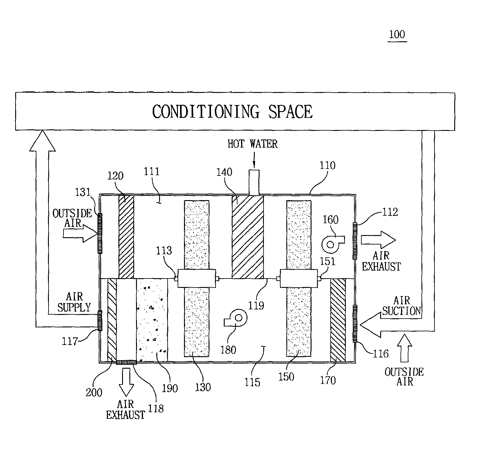
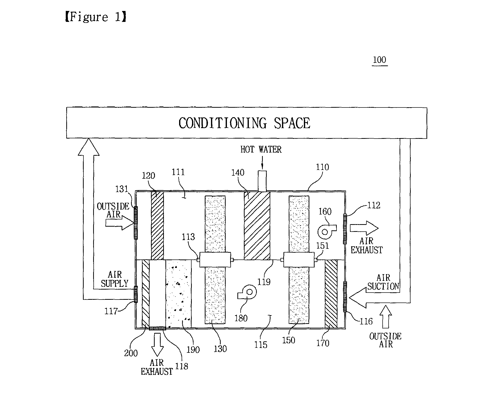
[0029]FIG. 1 is a view illustrating the configuration of a dehumidifying cooling device for district heating according to the present invention.

[0030]Referring to FIG. 1, the dehumidifying cooling device 10...


PUM


Abstract

A dehumidifying cooling device for district heating is developed that comprising; a case with partitions divided into interior, which are a wet channel consisting of an outside air suction, exhaust and a dry channel for circulated air suction from conditioning area and air supply; a rotating sensible heat exchanger to heat exchange outside air of wet channel with the circulated air in the dry channel; a heating coil between the sensible heat exchanger and the exhaust for raising the temperature of outside air; a dehumidifying wheel for adsorbing and removing moisture contained in the circulated air; the dehumidifying wheel being regenerated by evaporating the adsorbed moisture thereby supplying the evaporated moisture into the high-temperature outside air in the wet channel, and a regenerative-evaporative cooler installed between the circulated air supply and the sensible heat exchanger for cooling the circulated air in the dry channel, the cooled circulated air delivered to the air supply.

Description

BACKGROUND OF THE INVENTION[0001]1. Field of the Invention[0002]The present invention relates to a dehumidifying cooling device for district heating, and more particularly, to a dehumidifying cooling device for district heating which can perform an air cooling operation using hot water supplied by large-scale or small-scale district heating systems and gas-fired or oil-fired boilers installed in individual households.[0003]2. Description of the Related Prior Art[0004]There is a developing prospect that the recent high oil prices are not a temporary problem, but will be continuously maintained and fixed. Therefore, the main energy consuming countries of the world will increasingly make great efforts to secure stable energy resources. With the effectuation of the Tokyo protocol dealing with reduction in the discharge of greenhouse gas for the sake of preventing global warming, it will be expected that the international pressure for the limitation of fossil energy use, the criterion of...

Claims


Application Information

Patent Timeline
Patent Type & Authority Applications(United States)
IPC IPC(8): F24D10/00F24F3/14F28D17/00F25D17/04F25D31/00F28F1/10
CPCF24F3/1423F24F2203/1024F24F2203/1032F24F2203/104F24F5/0042F24F2203/1072F24F2203/1084Y02E20/14F24F2203/1056F24F3/14F25B5/00F24F7/08
Inventor YOON, SEOK-MANNLEE, DAE-YOUNGLEE, HOONKANG, CHANG-KUJEONG, SUNG-OOK
Owner KOREA DISTRICT HEATING CORP
Why Eureka
Try Eureka