Dual clutch transmission

a clutch transmission and clutch technology, applied in mechanical equipment, transportation and packaging, gearing, etc., can solve the problems of considerable limitations in the possibility of installing it in a vehicle, considerable space is necessary for their installation, etc., and achieve the effect of reducing the installation space requirements and cost-effectively

Active Publication Date: 2010-08-26
ZF FRIEDRICHSHAFEN AG
View PDF12 Cites 3 Cited by
  • Summary
  • Abstract
  • Description
  • Claims
  • Application Information

AI Technical Summary

Benefits of technology

[0006]The object of the present invention is to propose a dual clutch transmission of the type described above, with which power-shifted transmission steps are implemented as cost-effectively as possible with as few components as possible and with minimum installation space requirements.
[0014]According to another embodiment, this alternative can provide that when the coupling device on the first countershaft is disengaged, the power take-off gear of the first countershaft is decoupled from the first countershaft, so that at least one first forward gear is shiftable as a winding path gear. The power take-off gear can further be decoupled from the second countershaft when the coupling device on the second countershaft is disengaged, so that at least a seventh forward gear can be shifted as a winding path gear. Finally, it is also possible that an idler gear of the second part transmission can additionally be connected to an idler gear of the first part transmission via the shift element on the second countershaft, so that at least one first reverse gear or the like may be shifted as a winding path gear via the activated shift element. In the above embodiment, a crawling gear can additionally be shifted as a winding path gear when the coupling device on the second countershaft is open.
[0015]With the dual clutch transmission according to the present invention, winding path gears can be implemented via at least one disengaged coupling device and via at least one engaged shift element, wherein toothed gear wheels of both part transmissions are coupled to one another in order to thus implement a power flow through both part transmissions. The respectively utilized coupling device separates the corresponding power take-off gear from the associated countershaft when the used coupling device is disengaged. Due to both shiftable power take-off gears on each countershaft, on the one hand, more winding path gears can be implemented than when only using one shift element, and on the other hand, the gear shifting can be better adjusted. The employed shift element is used in this case for coupling two idler gears and thus causes the transmission input shafts to interact with one another.
[0020]Conceivably the specified arrangement options of the toothed gear wheels can be varied, and the number of toothed gear wheels as well as the number of the coupling devices can be changed in order to implement additional power-shifted and non-power-shifted gears and to achieve savings of installation space and parts in the proposed dual clutch transmission. In particular, fixed gears of dual gear planes can be divided into two fixed gears for two single gear planes. Gear ratio changes can be improved in this way. Apart from that, it is possible to interchange the countershafts. The part transmissions can also be interchanged, i.e. mirrored about a vertical axis. In this way, hollow shaft and solid shafts are swapped. For example, this makes it possible to arrange the smallest gear wheel on the solid shaft in order to further optimize the use of the available installation space. Moreover, adjacent gear planes can be interchanged, for example, in order to optimize a shaft deflection and / or optimally connect a shifting actuation system. In addition, the respective arrangement position of the coupling devices in the gear plane can be varied. Furthermore, the direction of action of the coupling devices can also be varied.
[0024]In an advantageous manner, the lower forward gears and reverse gears can be actuated via a starting and / or shift clutch in order to thus concentrate higher loads on this clutch allowing the second clutch to be more efficiently designed in terms of installation space and costs. In the proposed dual clutch transmission, the gear planes can in particular be arranged such that starting is possible via the inner transmission input shaft or via the outer transmission input shaft, and thus via the respectively more suitable clutch, which is also made possible with a concentric, radially nested construction of the dual clutch transmission. In addition, the gear planes can accordingly be arranged and / or interchanged in mirror symmetry. It is also possible that the countershafts are arranged in an interchangeable and / or mirrored manner.

Problems solved by technology

In order to implement the desired transmission steps in the known dual clutch transmissions, a plurality of gear planes are required, such that a considerable amount of space is necessary for their installation.
This results in an undesired extension of the overall length in the axial direction so that the possibilities of installing it in a vehicle are considerably limited.

Method used


Image

  • Dual clutch transmission
  • Dual clutch transmission
  • Dual clutch transmission

Examples


Embodiment Construction

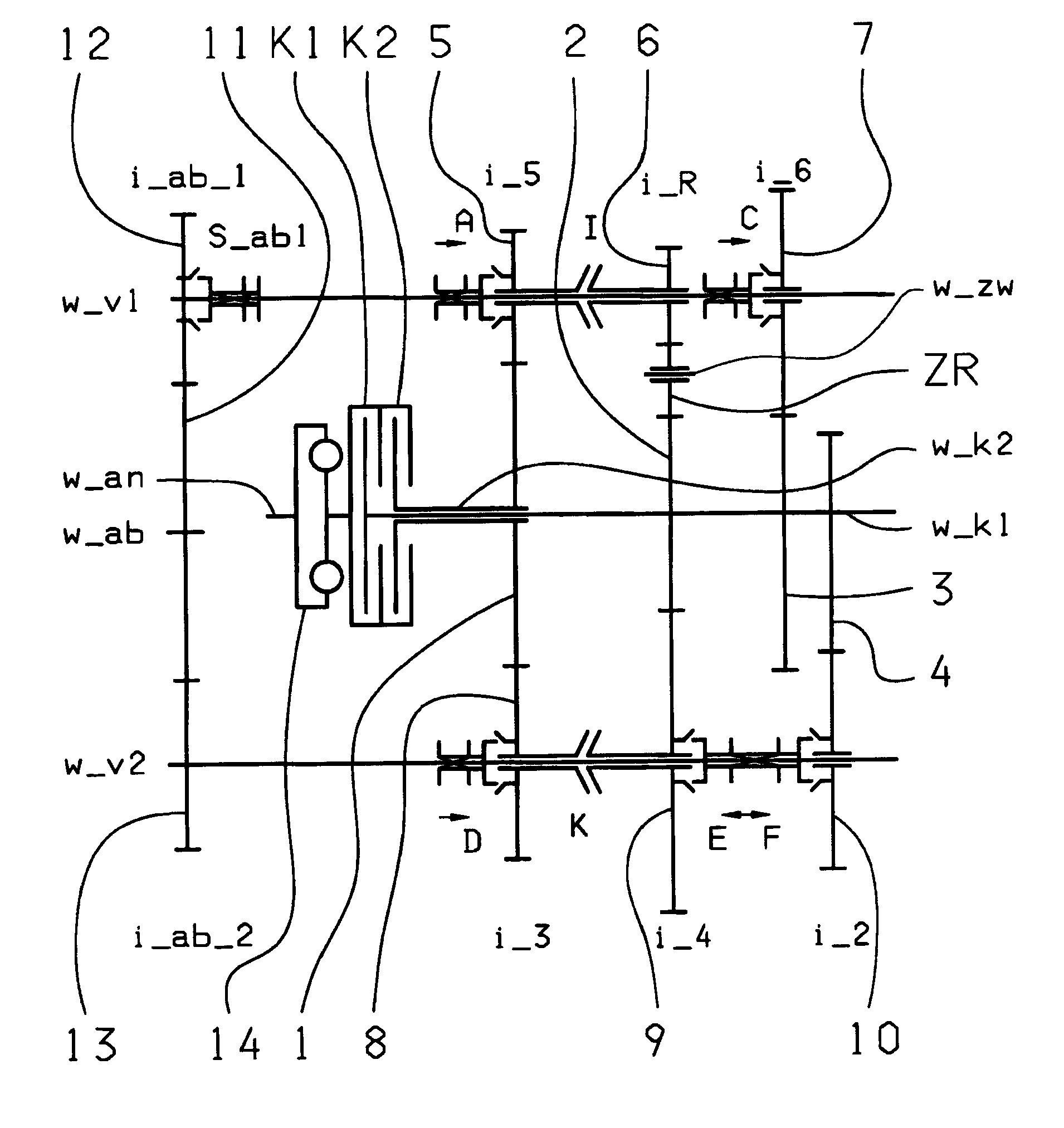
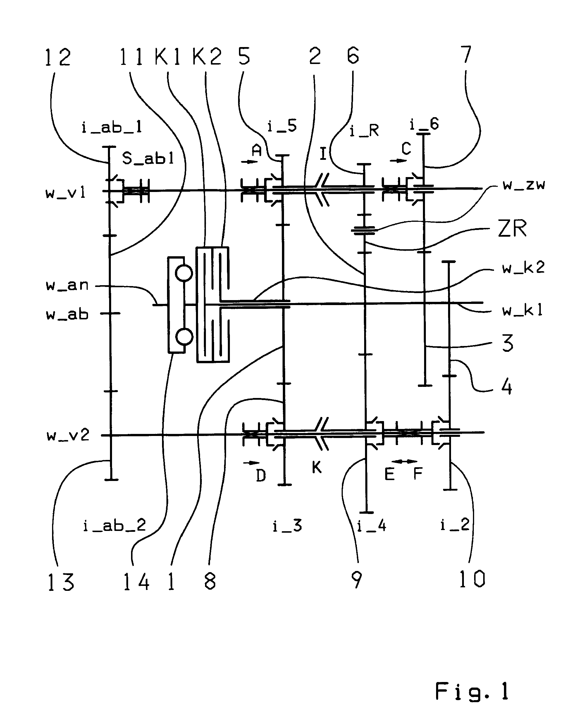
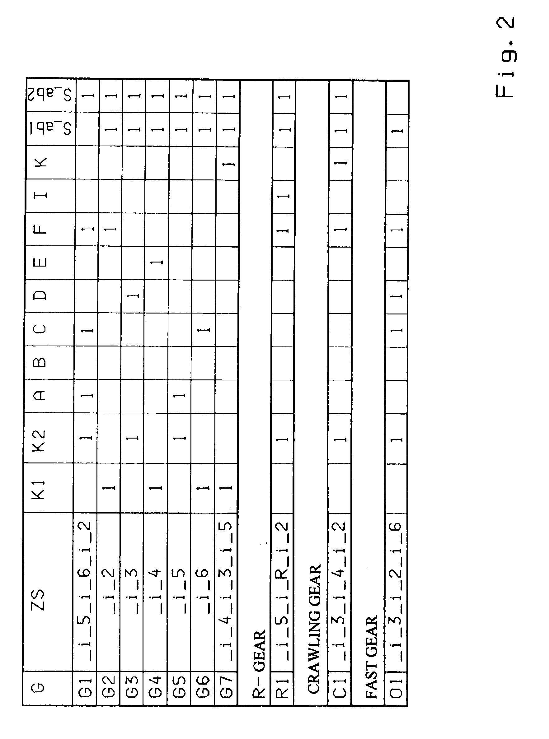
[0035]FIGS. 1, 3, 5 and 7 each show a possible construction variant of a seven-gear dual clutch transmission. The shift patterns corresponding to each of the construction variants are shown in FIGS. 2, 4, 6 and 8.

[0036]Independent of the respective construction variants, the seven-gear dual clutch transmission comprises two clutches K1, K2, whose input sides are connected to an input shaft w_an, and whose output sides are each connected to one of two transmission shafts w_K1, w_K2 that are arranged coaxially to one another. In addition, a torsional vibration damper 14 can be arranged on the input shaft w_an. Two countershafts w_v1, w_v2 are further provided, on which gear wheels are rotatably mounted as idler gears 5, 6, 7, 8, 9, 10. Gear wheels configured as fixed gears 1, 2, 3, 4 are non rotationally fixed on both transmission input shafts w_K1, w_K2, the gear wheels at least partially meshing with the idler gears 5, 6, 7, 8, 9, 10.

[0037]Several activatable coupling devices A, B, ...


PUM


Abstract

A dual clutch transmission having countershafts, idler gears and input shafts with gears which engage with the idler gears. The countershafts have a power take-off gear that is coupled to an output shaft. Shift elements connect gear wheels to engage forward and reverse gears. The transmission has two dual gear planes and two single gear planes, one idler gear of the countershafts being respectively associated with a fixed gear of one of the transmission input shafts in each of the dual gear planes. An idler gear in each dual gear plane is utilized for two gears and one idler gear of one countershafts associating with an input shaft fixed gear to shift at least one winding path gear via at least one shift element on each countershaft, and at least one winding path gear can be shifted with a coupling device associated with the take-off gear of the first countershaft and is disengaged.

Description

[0001]This application is a National Stage completion of PCT / EP2008 / 063421 filed Oct. 8, 2008, which claims priority from German patent application serial no. 10 2007 049 264.4 filed Oct. 15, 2007.FIELD OF THE INVENTION[0002]The present invention relates to a dual clutch transmission for a vehicle.BACKGROUND OF THE INVENTION[0003]From the document DE 103 05 241 A1, a six- or seven-gear dual clutch transmission is known. The dual clutch transmission comprises two clutches, each of which is connected on their input sides to the input shaft and on their output sides to one of both transmission input shafts. Both of the transmission input shafts are arranged coaxially with respect to one another. Two countershafts are further arranged axially parallel to both transmission input shafts, and have idler gears that mesh with fixed gears of the transmission input shafts. Furthermore, the coupling devices are held rotationally fixed but axially shiftable to the countershafts in order to allow...

Claims


Application Information

Patent Timeline
Patent Type & Authority Applications(United States)
IPC IPC(8): F16H3/16
CPCF16H3/006F16H3/093F16H2003/0807F16H2003/0931Y10T74/19228F16H2200/0056F16H2200/006F16H2200/0065Y10T74/19233F16H2200/0026
Inventor GUMPOLTSBERGER, GERHARDWAFZIG, JUERGENREISCH, MATTHIASRIEGER, WOLFGANGDREIBHOLZ, RALF
Owner ZF FRIEDRICHSHAFEN AG
Why Eureka
Try Eureka