
Flare-bang projectile

a projectile and projectile body technology, applied in the field of shotgun ammunition, can solve the problems of inaccurate targeting, less than ideal as a less-lethal weapon or deterrent force, and the weighty mass is not disclosed in the projectile for greater distance, accuracy, stability, etc., and achieves greater stability in flight and greater accuracy in targeting

Active Publication Date: 2010-08-26
COMBINED SYST
View PDF20 Cites 76 Cited by
  • Summary
  • Abstract
  • Description
  • Claims
  • Application Information

AI Technical Summary

Benefits of technology

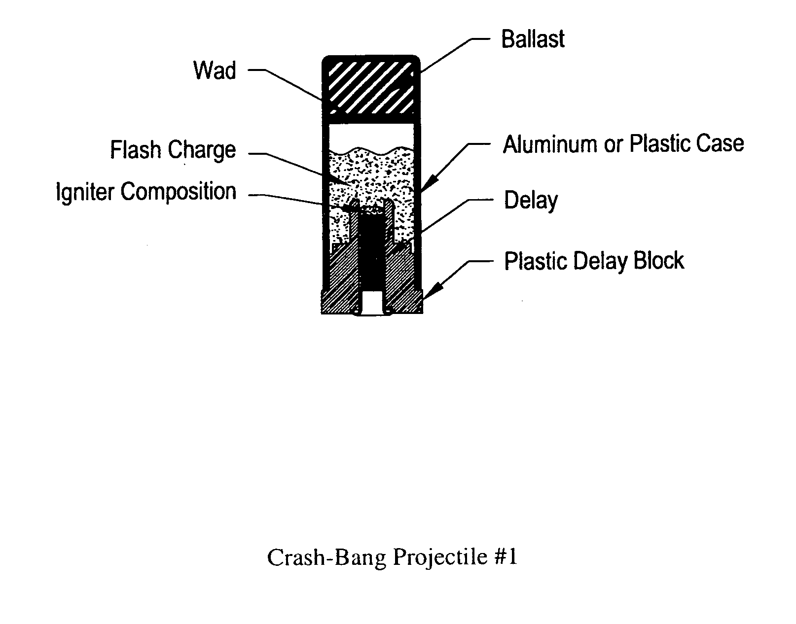
"The present invention provides a shotgun cartridge with improved stability and accuracy in targeting. The cartridge has a frangible ballast that disintegrates into low-energy fragments, providing a deterrent at extended ranges. The ballast is made of zinc and graphite powder and is located at the front of the projectile. The transfer charge is located at the end of the projectile and helps reduce drag and increase range. The flare charge is lit by the starter composition and provides a warning signal. The invention has improved stability and accuracy in targeting compared to flash-bang cartridges."

Problems solved by technology

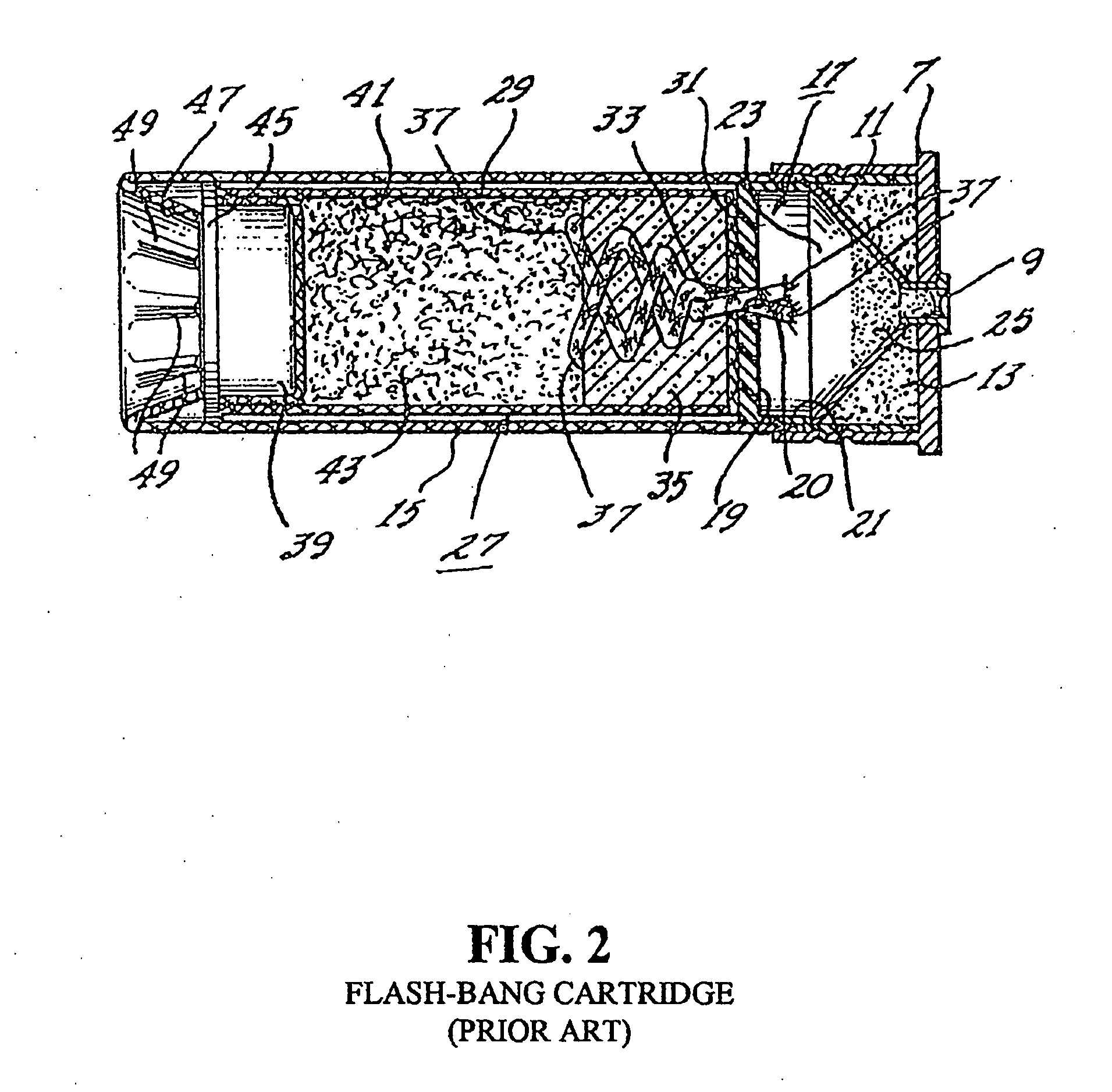
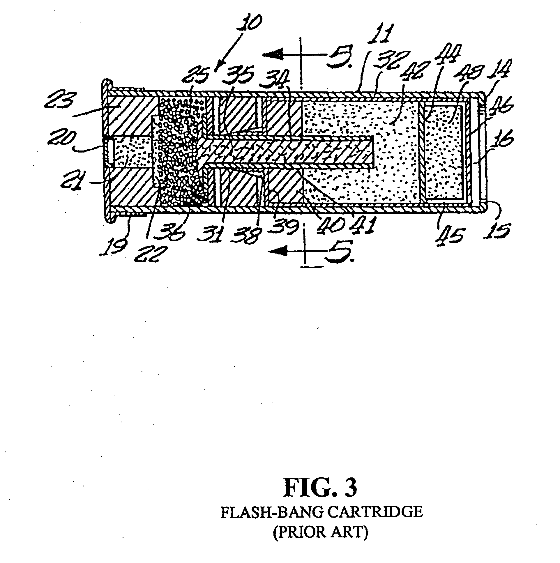
However, these prior art flash-bang cartridges have several shortcomings which make them less than ideal as a less-lethal weapon or deterrent force.
6, lines 1-3); however, the '456 patent's weighty mass is located in the rear of the projectile, which causes tumbling in flight and, thus, inaccurate targeting.
However, the '144 patent does not disclose a weighty mass positioned in the projectile for greater distance, accuracy, and stability.
Because of the lack of ballistic weight, the projectile described by the '144 patent can not achieve long or accurate trajectories, but will instead tumble in flight and fall quickly to the ground.

Method used


Image

  • Flare-bang projectile
  • Flare-bang projectile
  • Flare-bang projectile

Examples


Embodiment Construction

[0030]The presently preferred embodiments of the present invention were originally developed in response to a U.S. Marine Corps request for shotgun rounds capable of delivering a “flash-bang”-type air burst at ranges of 400 feet, 600 feet and 800 feet. The rounds were intended for less-lethal use both as a deterrent and as a means for determining the intent of potentially hostile groups at extended stand off ranges. The following design requirements were set forth in the U.S. Marine Corps request:

[0031]1. Standard shotgun shell cartridges were to be used;

[0032]2. Standard propelling methods were to be used, i.e., igniting nitrocellulose based smokeless propellants in the shot shell (no miniature rocket motors); and

[0033]3. Projectile must disintegrate into low energy fragments upon detonation.

[0034]There is a key problem when attempting to meet this combination of requirements. The desire for a projectile that can travel up to 800 feet requires a fairly heavy weight as ballast, beca...


PUM


Abstract

A flare-bang projectile is comprised of a weighty ballast in the front leading edge, a flash-bang charge, a transfer charge and a flare charge that is lit by a starter composition located at the rear of the flare charge. When the flare charge is ignited such that it burns during the flight of the projectile, an the projectile path is indicated to thereby provide warning signaling.

Description

RELATED APPLICATIONS[0001]The present application claims priority from U.S. Provisional Application Ser. No. 60 / 807,173 filed Jul. 12, 2006 and is a continuation-in-part of U.S. patent application Ser. No. 11 / 328,753 filed Jan. 10, 2006, which is a continuation of U.S. patent application filed Ser. No. 10 / 691,404 filed Oct. 21, 2003, which claimed priority from U.S. Provisional Patent Application Ser. No. 60 / 419,891 filed Oct. 21, 2002, each of which are hereby incorporated by reference in their entirety.BACKGROUND OF THE INVENTION[0002]1. Field of the Invention[0003]The present invention relates generally to the field of shotgun ammunition, and more particularly, to a shotgun cartridge capable of exploding with a loud noise and producing low mass, low energy fragments which do not pose a serious risk of injury to persons close to the explosion and which provides a bright visible light during flight of the cartridge to thereby provide visual signaling.[0004]2. Description of the Rel...

Claims


Application Information

Patent Timeline
Patent Type & Authority Applications(United States)
IPC IPC(8): F42B12/36F42B33/00
CPCF42B4/26F42B12/42F42B7/02
Inventor BRUNN, MICHAEL
Owner COMBINED SYST
Learn More