Well gauging system and method

Inactive Publication Date: 2010-08-26
RELEVANT
View PDF21 Cites 3 Cited by
  • Summary
  • Abstract
  • Description
  • Claims
  • Application Information

AI Technical Summary

Benefits of technology

[0007]The well gauging system includes two containment vessels, a common inlet line to the vessels with divert valves on each inlet line of the vessels which may be opened or closed by a programmable logic controller (PLC), a common outlet line to the vessels, a common gas line attached to the top of each vessel which has low and high pressure regulators allowing control of the vessel's internal pressure, a vertical level indication device for controlling level in each vessel, a

Problems solved by technology

A particular problem with respect to efficient and accurate measurement of the aforementioned pro

Method used


Image

  • Well gauging system and method
  • Well gauging system and method

Examples


Embodiment Construction

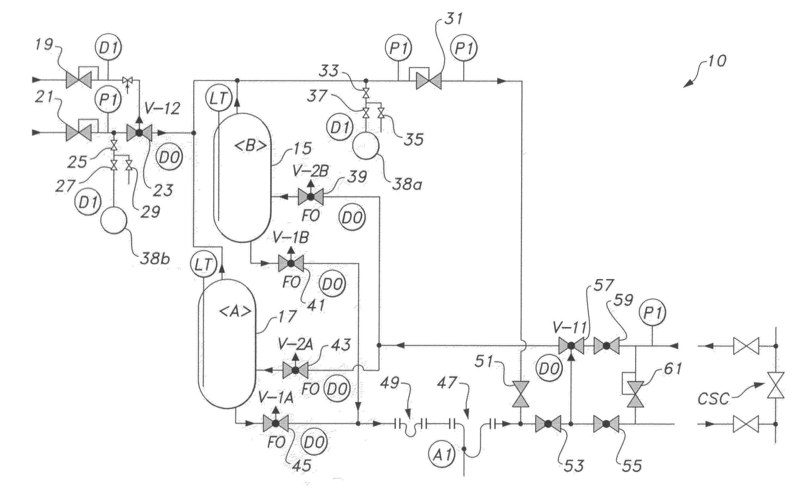
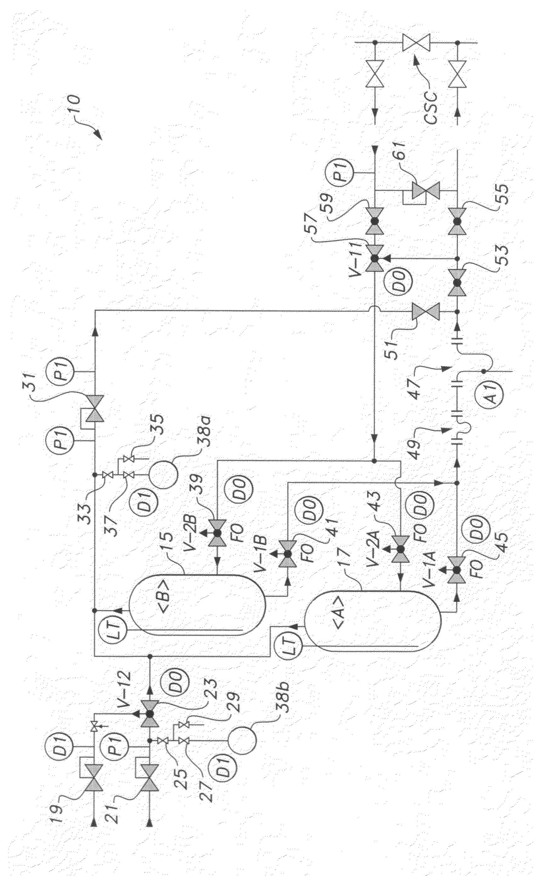
[0011]As shown in the drawing, the well gauging system includes a first containment vessel 17 and a second containment vessel 15. A typical customer source CSC at a well site provides a valve regulated stream into the test system 10 and a valve regulated return stream back to the customer source CSC. A common inlet line to the vessels is comprised of a pressure safety valve 61, which shunts some of the source stream back to the return stream when the source stream input to the valve exceeds a predetermined value. The input stream is then routed through a manual isolation valve 59. Source stream regulation is achieved via 3 way bypass valve V-1157, which can dump excessive source pressure back into the return stream.

[0012]The common inlet includes divert valves on each inlet line of the vessels. For example, vessel A 17 has inlet divert valve V-2A 43 while vessel B15 has inlet divert valve V-2B 39. The inlet line divert valves 39 and 43 may be opened or closed by a programmable logic...


PUM


Abstract

The well gauging system and method includes two containment vessels, a common inlet line to the vessels with divert control valves on each inlet line of the vessels being controlled by a programmable logic controller (PLC), a common outlet line to the vessels, a common gas line attached to the top of each vessel, which has low and high pressure regulators allowing control of the vessel's internal pressure, a vertical level indication device for controlling level in each vessel, a water cut meter used to report water cut of the production stream, a coriolis meter, valves, gas cylinder, a controller for process control of well testing, storing results, and sending results to a customer's central computer. The method of using two vessels allows more time for the emulsion to separate, thus increasing the accuracy of the oil, water, and gas measurements.

Description

CROSS-REFERENCE TO RELATED APPLICATION[0001]This application claims the benefit of U.S. Provisional Patent Application Ser. No. 61 / 202,389, filed Feb. 24, 2009.BACKGROUND OF THE INVENTION[0002]1. Field of the Invention[0003]The present invention relates generally to automatic well test systems. More specifically, the invention is a well gauging system and method for testing production wells, including measuring and determining the amount of oil produced per day, water produced per day, and gas produced per day on a well.[0004]2. Description of the Related Art[0005]In the oil and gas production industry it would be desirable to have an automatic well test system that could operate in an efficient and accurate manner while testing production wells for amount of oil produced per day, water produced per day, and gas produced per day. A particular problem with respect to efficient and accurate measurement of the aforementioned production amounts is that many test systems do not allow for...

Claims


Application Information

Patent Timeline
IPC IPC(8): F16K11/00
CPCE21B47/10Y10T137/877Y10T137/0318E21B44/00
Inventor MEANS, STEPHEN R.
Owner RELEVANT
Why Eureka
Try Eureka