
Bottle treatment system having safety unit

a technology of safety unit and treatment system, which is applied in the direction of liquid handling, instruments, transportation and packaging, etc., can solve the problems of cleaning or maintenance operation delay

Active Publication Date: 2010-08-26
KRONES AG
View PDF4 Cites 2 Cited by
  • Summary
  • Abstract
  • Description
  • Claims
  • Application Information

AI Technical Summary

Benefits of technology

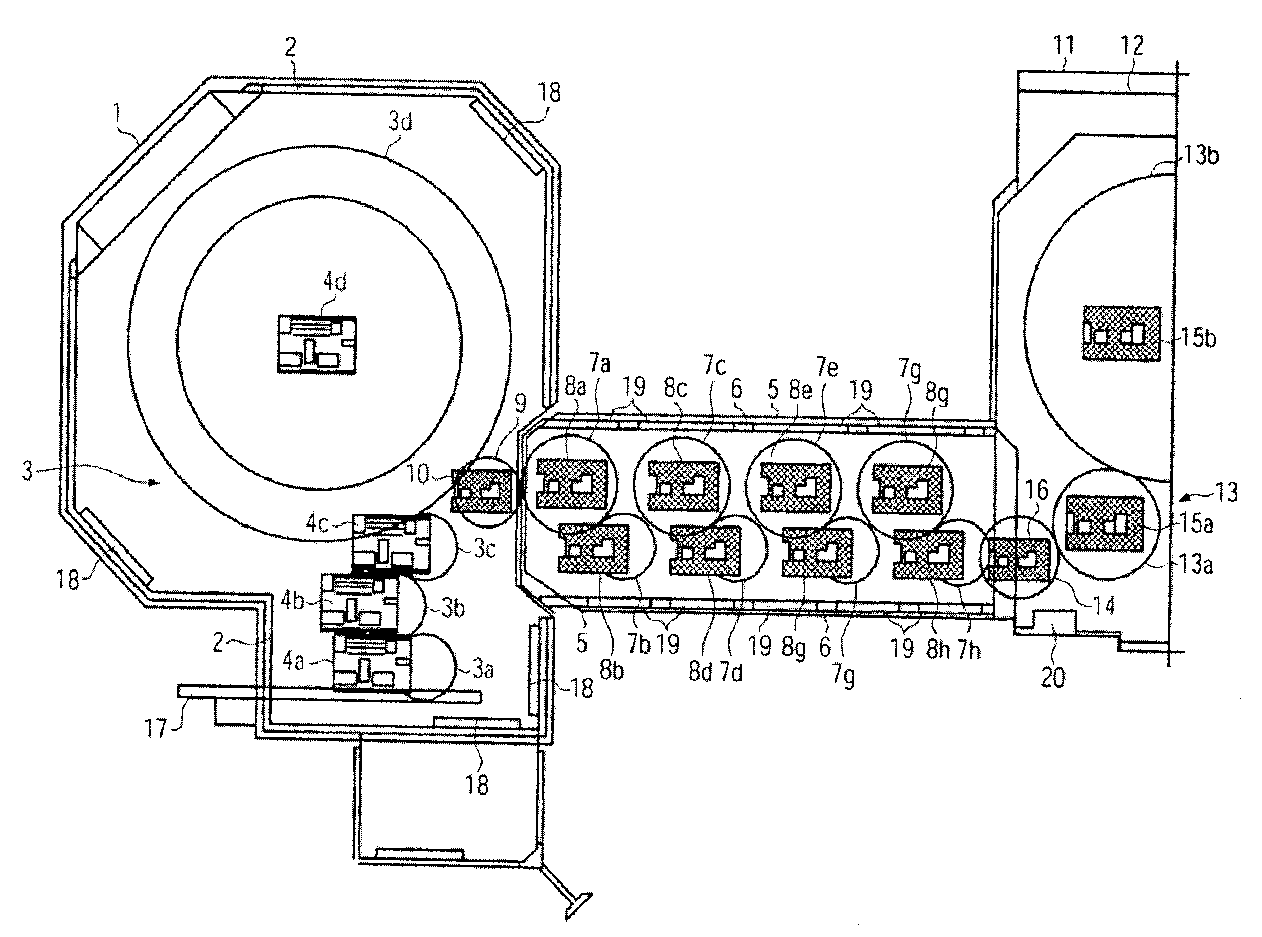
The present patent is about a bottle treatment system with a safety unit that improves operational processes while ensuring safety aspects. The system is designed with flexible system components that can be easily modulated. The safety unit includes two protective regions delimited by respective protective doors, which are shut off when the protective doors are opened. The shut-off device is designed to prevent any risk of injury to operators during maintenance and cleaning works. The machines in the protective regions have individual drives with corresponding sensors or switches to control their operation. The shut-off device can also interrupt the drive supply to the machines and machine parts. The use of servo drives in the system further reduces the risk of injury. Overall, the safety unit improves operational processes and saves costs.

Problems solved by technology

Here, there arises a problem in particular in the transitional region of adjacent protective regions, where usually the transport device for transferring the bottles from the one to the next machine is provided, in that the personnel must be protected from an operation of the transport device if, for example, parallel maintenance and cleaning operations must be performed independently at the machines arranged in the adjacent protective regions.
This measure, however, is very time consuming, leads to delays during the cleaning or maintenance operation, respectively, and is very cost-intensive due to the provision of the mechanical protection.

Method used


Image

  • Bottle treatment system having safety unit
  • Bottle treatment system having safety unit

Examples


Embodiment Construction

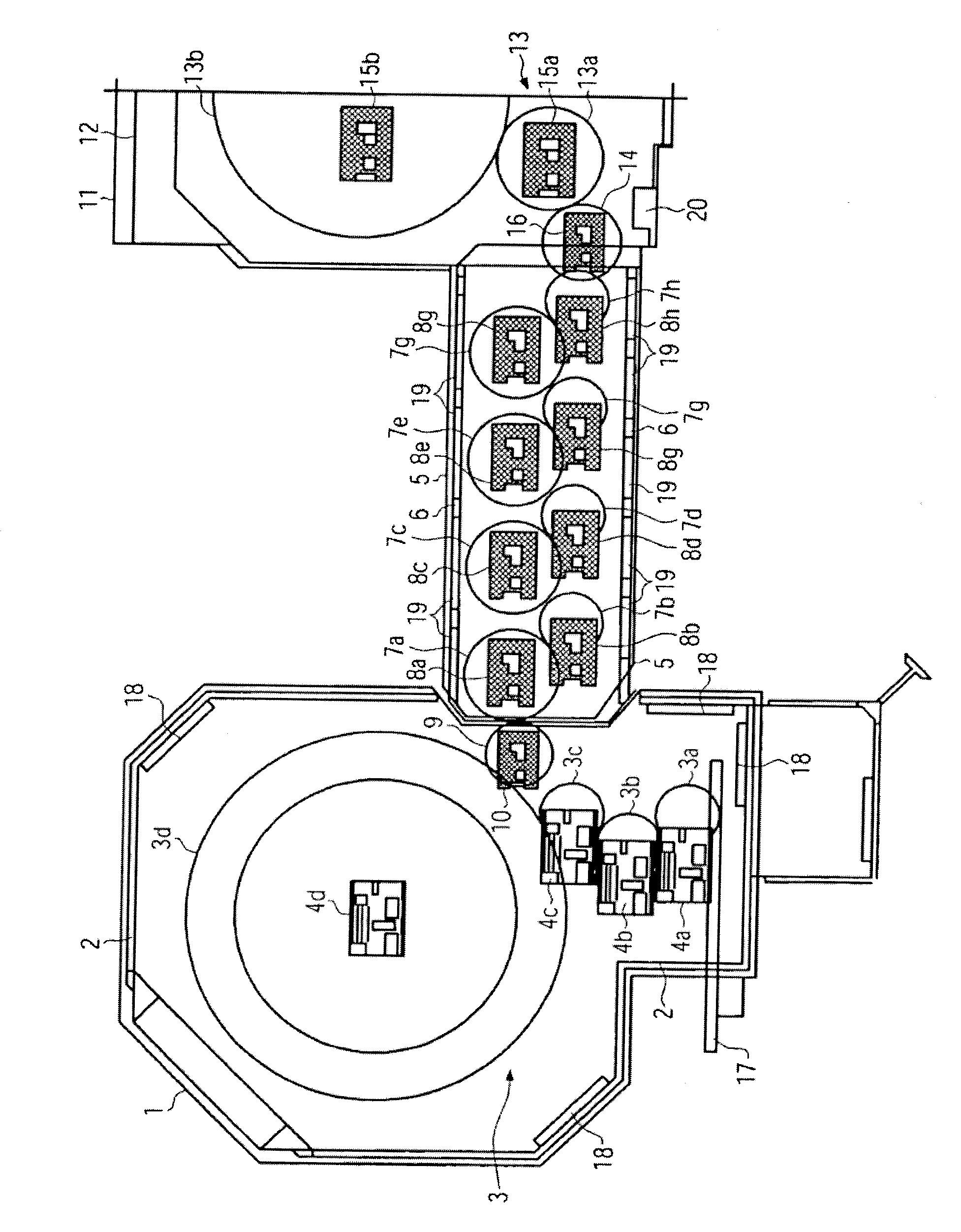
[0020]The figure shows a schematic representation of an embodiment of a bottle treatment system having a safety unit according to the present disclosure. The bottle treatment system comprises a first protective region 1, a second protective region 5 and a third protective region 11. The protective regions 1, 5 and 11 are arranged such that the first protective region 1 directly follows the second protective region 5, and the second protective region 5 directly follows the third protective region 11. The individual protective regions 1, 5 and 11 each comprise a protection 2, 6 and 12. Here, for the sake of simplicity, only half of the third protective region 11 with its third protection 12 is represented. Further protective regions can follow the third protective region I 1. In the first protective region 1, a machine 3 with four machine parts 3a, 3b, 3c, 3d, designed as carousel-type machine parts are provided. Each of the machine parts 3a, 3b, 3c and 3d comprises an individual driv...


PUM


Abstract

A bottle treatment system having a safety unit that improves the operational process, including a first accessible safety region, a second accessible safety region and a shut-off device. The first safety region is delimited by a first protection in which a first machine has a drive associated with the first protective region. The second accessible protective region is delimited by a second protection direction following the first protection, with a second machine having at least one further drive associated to the second protective region. A bottle transport from the first machine to the second machine is provided via a transport device, as provided with an individual drive and exceeds the protective region. The shut-off device turns off the machine drive associated with at least one of the respective protective regions and the drive of the transport device exceeding the protective region, if access to protective region is detected.

Description

CROSS-REFERENCE TO RELATED APPLICATION[0001]The present application claims the benefit of priority of International Patent Application No. PCT / EP2008 / 008301, filed Sep. 30, 2008, which application claims priority of German Patent Application No. 102007047733.5, filed Oct. 5, 2007. The entire text of the priority application is incorporated herein by reference in its entirety.FIELD OF THE DISCLOSURE[0002]The present disclosure relates to a bottle treatment system having a safety unit, such as used in beverage bottling operations.BACKGROUND[0003]Such a bottle treatment system is known from the generic DE 199 28 325. The bottle treatment system is composed of three subsequently arranged machines, which are a stretch blow molding machine with preceding preform feed, a rinsing machine in the form of a rinser as well as a filling machine with an integrated closing station. Each of these machines is protected by a housing whereby a protective region is defined for each of these machines. T...

Claims


Application Information

Patent Timeline
Patent Type & Authority Applications(United States)
IPC IPC(8): B65G43/00
CPCB65G43/00B65G69/00B65G2207/40F16P3/08B67C7/00B67C7/0073B67C3/007
Inventor ZECH, THOMAS
Owner KRONES AG
Learn More