Packet processing device by multiple processor cores and packet processing method by the same

Inactive Publication Date: 2010-08-26
HITACHI LTD
View PDF9 Cites 25 Cited by
  • Summary
  • Abstract
  • Description
  • Claims
  • Application Information

AI Technical Summary

Benefits of technology

[0023]According to one embodiment of the present invention, the virtual environment is built for the each user or service, and the user's packet is transferred

Problems solved by technology

When performing plural processings with one piece of hardware as described above, a tas

Method used


Image

  • Packet processing device by multiple processor cores and packet processing method by the same
  • Packet processing device by multiple processor cores and packet processing method by the same
  • Packet processing device by multiple processor cores and packet processing method by the same

Examples


first embodiment

[0046]First, the present invention will be explained.

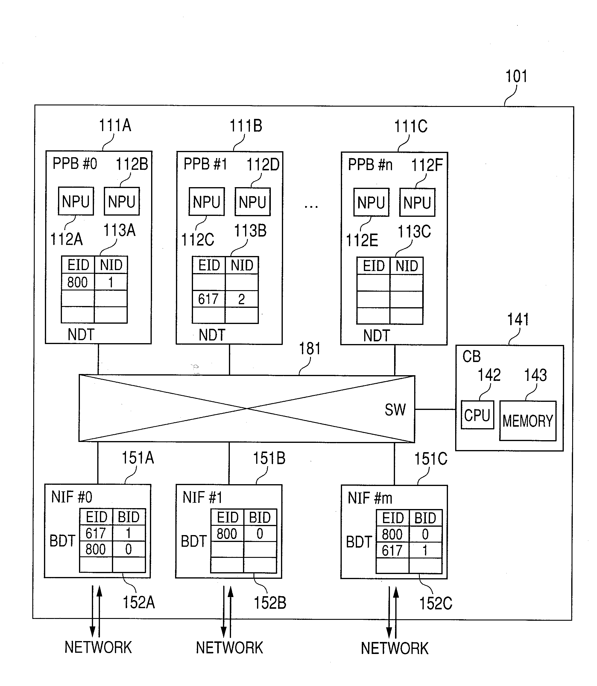
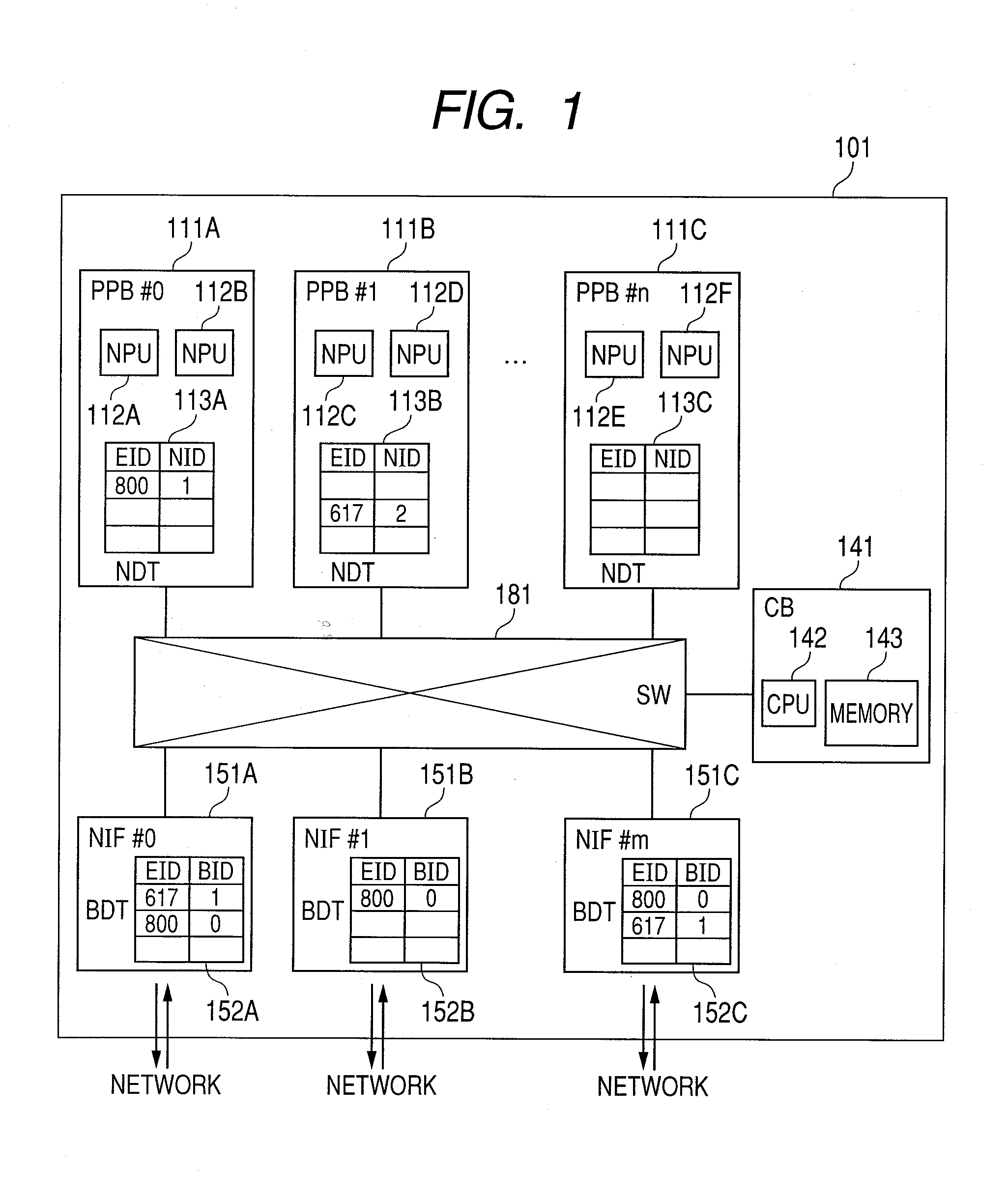
[0047]FIG. 1 is a block diagram showing an entire configuration of the packet processing device 101 according to the first embodiment of the present invention.

[0048]The packet processing device 101 consists of one or plural packet processing boards (PPB) 111, one or plural network interfaces (NIF) 151 each of which are connected to a network, a control board (CB) 141, and a switch fabric 181 for connecting them.

[0049]FIG. 1 shows the packet processing device 101 equipped with n packet processing boards 111 and m network interfaces 151 as an example. However, FIG. 1 shows only three of the n packet processing boards 111 as packet processing boards 111A, 111B, and 111C, and shows only three of the m network interfaces 151 as network interfaces 151A, 151B, and 151C. When giving an explanation common to all of the packet processing boards 111A to 111C in this embodiment, these are also generically named and described a packet processi...

second embodiment

[0155]Hereafter, the present invention will be explained.

[0156]FIG. 10 is a block diagram showing the entire configuration of the packet processing system according to the second embodiment of the present invention.

[0157]The system shown in FIG. 10 realizes a function equivalent to that of the packet processing device 101 in the first embodiment.

[0158]Specifically, the system shown in FIG. 10 has plural packet processing device (PPE) 1011, the third layer switch 1012 and a control unit 1013. The plural packet processing devices (PPE) 1011 are connected with the third layer switch 1012 by 10-Gbit Ethernet. The third layer switch 1012 further carries a 10-Gbit Ethernet interface (illustration omitted), and is connected with other devices thereby.

[0159]The control unit 1013 is connected with the third layer switch 1012 directly or indirectly. The control unit 1013 includes the control board 141, and the control board 141 includes the general purpose CPU 142 and the main storage 143.

[01...


PUM


Abstract

A packet processing device includes multiple processor cores and memory connected to the multiple processor cores, upon reception of a load request of a program, selects a processor core to which the program has not yet been loaded, loads the program to the selected processor core, retains first association information that associates attribute information specified by the load request with the processor core to which the program has been loaded, upon reception of the packet, specifies the attribute information corresponding to the received packet, and transfers the received packet to the processor core corresponding to the specified attribute information.

Description

CLAIM OF PRIORITY[0001]The present application claims priority from Japanese patent application JP 2009-037933 filed on Feb. 20, 2009, the content of which is hereby incorporated by reference into this application.FIELD OF THE INVENTION[0002]The present invention relates to processing of a data stream such as a packet stream in a network.BACKGROUND OF THE INVENTION[0003]One object of the data stream processing in the network is to provide plural advanced services that cannot coexist on a network node to plural users, and further to enable addition / deletion of a service and alteration of a content of the service during a network operation. In order to provide such a service with one physical network, it is required to virtualize the network, that is, to show as if the each user or each user group is using an independent network. In addition, in each network node, in order to process an advanced service, it is required to process a packet stream that is inputted from a communication l...

Claims


Application Information

Patent Timeline
IPC IPC(8): H04L12/56G06F15/76G06F9/06G06F15/177H04L45/58
CPCG06F9/445
Inventor KANADA, YASUSI
Owner HITACHI LTD
Why Eureka
Try Eureka