Single probe microwave power measuring device with display and method thereof

A measuring device and microwave power technology, applied in the field of testing, can solve the problems of cumbersome connection, large space occupation, unsuitable for on-site debugging, etc., and achieve the effect of flexible programming and convenient reading

Inactive Publication Date: 2017-05-31
THE 41ST INST OF CHINA ELECTRONICS TECH GRP
View PDF10 Cites 5 Cited by
  • Summary
  • Abstract
  • Description
  • Claims
  • Application Information

AI Technical Summary

Problems solved by technology

[0002] At present, the measurement of microwave and millimeter wave continuous wave signal power generally adopts the form of power test host + multi-core cable + power probe. The existing microwave power measurement instrument architecture of host + cable + power probe, because the host needs to realize power conversion, Display, keys, various external interfaces and basic functions of the instrument occupy a large volume (generally: 330mm×220mm×100mm, probe: 40mm×40mm×125mm), and occupy a large cabinet space when building a test system. It requires 220V power supply and program-controlled interfaces such as GPIB, serial port or network port. The connection is cumbersome and generally limited to laboratory use, especially not suitable for on-site debugging, monitoring and production line use; and when multiple adjacent power ports need to be connected During the test, multiple power meter hosts, cables and power probes need to be used at the same time, which takes up a lot of space, and the program control connection is more cumbersome and the cost is higher

Method used


Image

  • Single probe microwave power measuring device with display and method thereof
  • Single probe microwave power measuring device with display and method thereof
  • Single probe microwave power measuring device with display and method thereof

Examples


Embodiment Construction

[0029] The following will clearly and completely describe the technical solutions in the embodiments of the present invention with reference to the accompanying drawings in the embodiments of the present invention. Obviously, the described embodiments are only some, not all, embodiments of the present invention. Based on the embodiments of the present invention, all other embodiments obtained by persons of ordinary skill in the art without making creative efforts belong to the protection scope of the present invention.

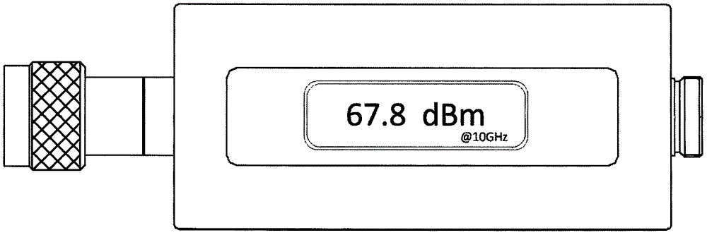
[0030] In the existing microwave power measurement instrument architecture, the mainframe usually adopts a larger desktop chassis design, which takes up a lot of space and requires AC 220V power supply, which is only suitable for laboratory workbenches; when building a test system, the power test mainframe also occupies Large cabinet space. Therefore, the application of the desktop structure in the field testing and maintenance of the current wireless communic...


PUM


Abstract

The invention provides a single probe microwave power measuring device with a display; the single probe microwave power measuring device comprises a simulation circuit and a digit circuit; the simulation circuit comprises a power sensing circuit, a pre-stage amplification circuit, a rear stage amplification circuit and an analog to digital conversion circuit; the simulation circuit is used for sensing and modulating power signals, and carrying out analog-to-digital conversion; the digit circuit comprises a digit signal processor, a temperature detection circuit, an OLED display circuit, a power source management circuit, and a USB interface circuit; the digit circuit is used for calibrating and compensating power test data, controlling the whole machine, and managing the power source. The USB interface supply is realized, so the measuring device is compact in structure; the single probe can be held by hand, is light in weight, and the shape is similar to a normal power probe matched with a power measuring host; an OLED display is arranged on the housing, and the measuring result can be read through the machine body OLED display under the condition in which only +5 V DC power source is provided.

Description

technical field [0001] The invention relates to the technical field of testing, in particular to a microwave power measuring device, and also to a microwave power measuring method. Background technique [0002] At present, the measurement of microwave and millimeter wave continuous wave signal power generally adopts the form of power test host + multi-core cable + power probe. The existing microwave power measurement instrument architecture of host + cable + power probe, because the host needs to realize power conversion, Display, keys, various external interfaces and basic functions of the instrument occupy a large volume (generally: 330mm×220mm×100mm, probe: 40mm×40mm×125mm), and occupy a large cabinet space when building a test system. It requires 220V power supply and program-controlled interfaces such as GPIB, serial port or network port. The connection is cumbersome and generally limited to laboratory use, especially not suitable for on-site debugging, monitoring and p...

Claims


Application Information

Patent Timeline
Patent Type & Authority Applications(China)
IPC IPC(8): G01R21/00G01R1/067G01R1/02G01R35/00
CPCG01R21/00G01R1/02G01R1/06711G01R1/06788G01R35/005
Inventor 赵浩徐达旺冷朋
Owner THE 41ST INST OF CHINA ELECTRONICS TECH GRP
Why Eureka
Try Eureka