Wireless Communications System for tool

a communication system and tool technology, applied in the field of wireless communication systems for tools, can solve the problems of high possibility of tool operation failure, communication errors, and negative influence of wire communications on tool convenience, and achieve the effect of reducing the installation space of transceivers and the number of installed transceivers

Active Publication Date: 2010-08-26
PANASONIC ELECTRIC WORKS POWER TOOLS
View PDF18 Cites 43 Cited by
  • Summary
  • Abstract
  • Description
  • Claims
  • Application Information

AI Technical Summary

Benefits of technology

[0014]Additionally, the transceiver may communicate with a plurality of tools having their respective identification numbers, the tools can be managed by a single transceiver, the number of installed transceivers and the transceiver installation space can be reduced, and a cost-saving can be achieved.

Problems solved by technology

In this case, it is preferable to use wireless communications as shown in Japanese Patent No. 2983124 and Japanese Patent Application Publication No. 2000-024945 rather than wire communications because the wire communications negatively affects the convenience of the tool.
However, there is possibility that there are various kinds of environmental noises, such as wireless LAN and the like, in the factory, thereby causing communications errors due to such noises during the wireless communications.
However, conventionally, a wireless communications frequency has to be fixed and cannot be changed in the field and, thus, it is required to make the wireless communications frequency changeable.
However, if many setting switches, including a DIP switch and the like, are provided with the tool, there can be a high possibility of a tool operation failure due to intrusion of foreign material such as iron powder and the like depending on the surrounding environment.
However, in such a case, when a plurality of tools is used in the factory, each of the tools needs to be connected to the PC to change the settings of all the tools, thus entailing an extremely poor working efficiency.

Method used


Image

  • Wireless Communications System for tool
  • Wireless Communications System for tool
  • Wireless Communications System for tool

Examples


first embodiment

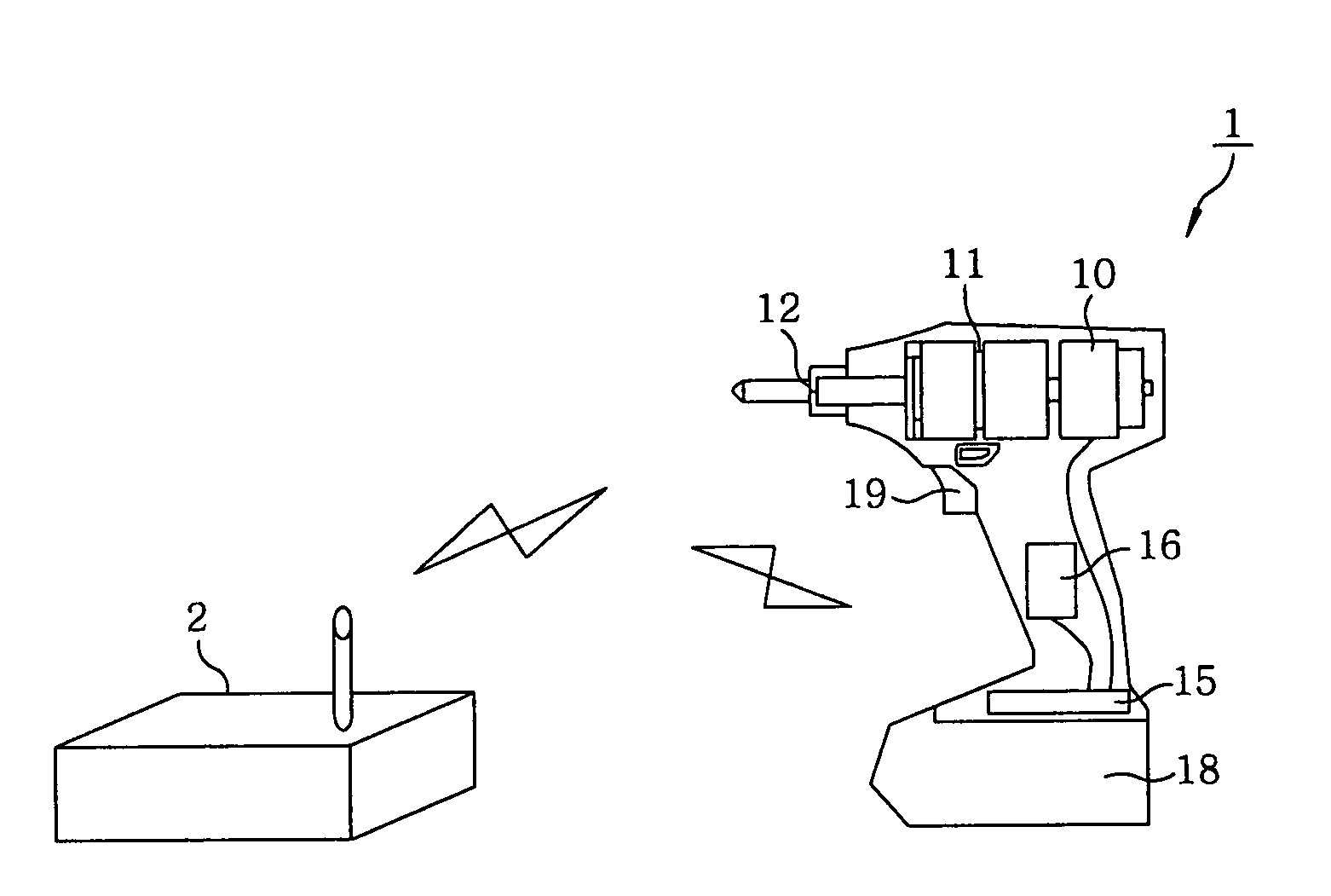
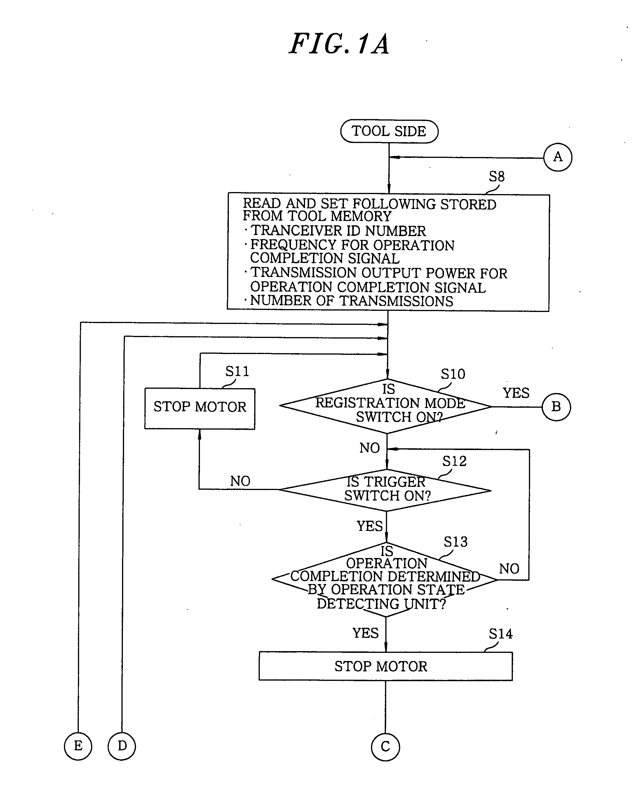
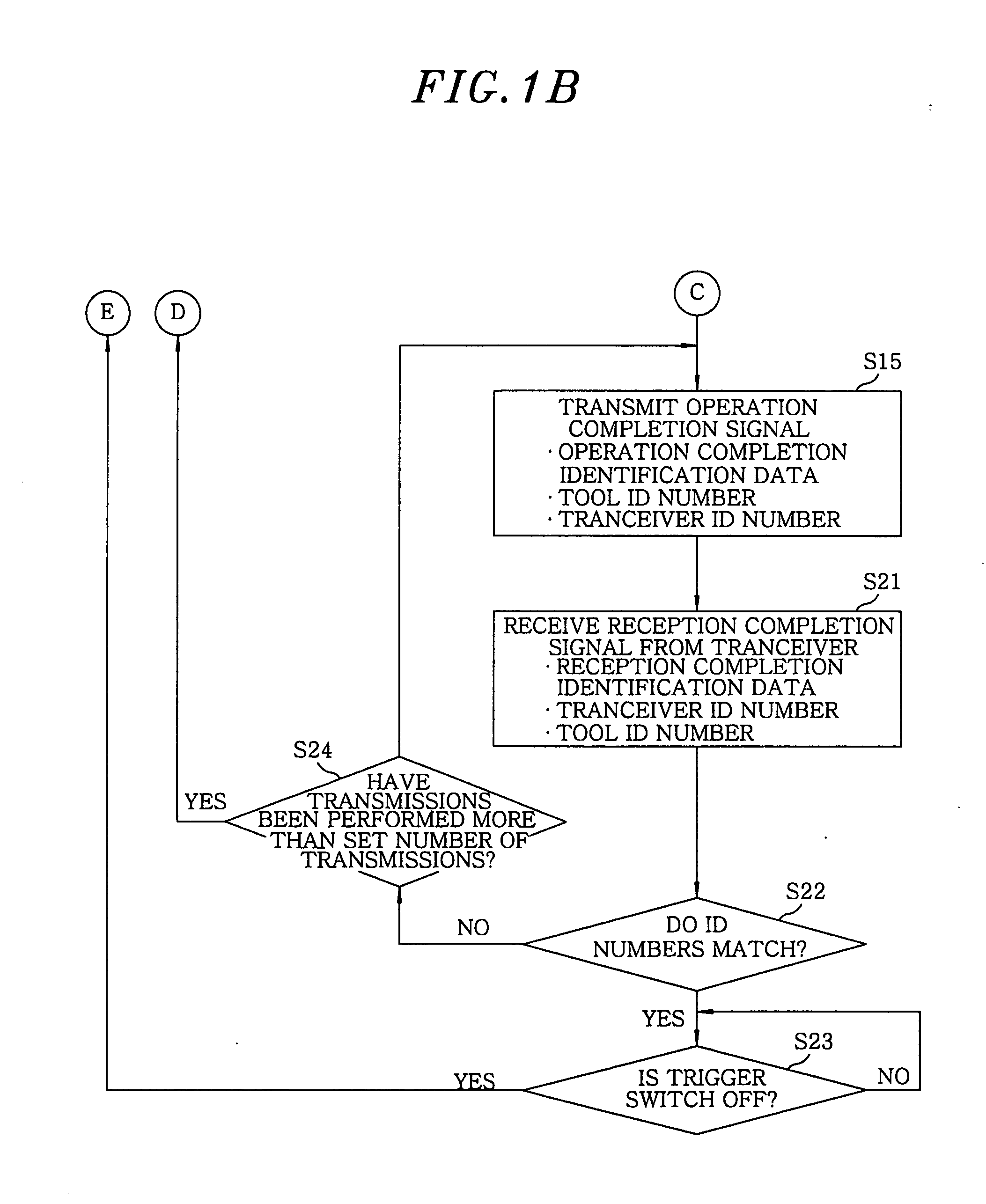
[0026]In a first embodiment of the present invention, an electric impact driver serves as a tool 1 in an illustrated example. As shown in FIGS. 3 and 4, the impact driver 1 includes a motor 10 as a rotational power source; a fastening unit 11 having a striking mechanism provided with a hammer and an anvil and outputting a rotation output of the motor 10, as a rotating stroke, to an output shaft 12; an operation state detecting unit 13 for detecting the state of a screw tightening operation by the fastening unit 11; a tool control unit 15 for controlling the operation of the motor 10 via a motor control unit 14; a wireless communications unit 16; and a mode setting unit 17. The impact driver 1 operates using as a power source a secondary battery in a battery pack 18 detachably attached to the impact driver 1. Reference numeral 19 shown in FIG. 3 is a trigger switch that turns on and off of the motor 10 and adjusts rpm (revolutions per minute) of the motor 10 by varying a voltage appl...

second embodiment

[0043]Although the basic configurations and functions of a second embodiment are the same as those of the first embodiment, the second embodiment of the present invention is different from the first embodiment in that the mode setting unit 17 (shown in FIG. 4) in the impact driver serving as a tool 1 is omitted and a remote controller 3 is included in the impact driver as shown in FIGS. 8 and 9, instead of the wireless communications parameter setting unit 22 shown in FIG. 4, so that a mode setting for the tool 1 and wireless communications parameters can be set and changed by the remote controller 3. Therefore, redundant description will be omitted, while distinctive configurations and functions will be described below. Further, like the wireless communications parameter setting unit 22, the remote controller 3 (a wireless communications parameter setting unit 30) includes, e.g., a DIP and the like to set wireless communications parameters to be described later.

[0044]The remote con...


PUM


Abstract

A wireless communications system includes a tool having a first wireless communications unit and a transceiver having a second wireless communications unit to receive a signal transmitted from the first wireless communications unit. Further, the transceiver has a setting unit for setting wireless communications parameters for wireless communications between the first and the second wireless communications unit, and the tool has a tool control unit for setting in the wireless communications unit the wireless communications parameters set by the setting unit and transmitted to the tool by wireless communication.

Description

FIELD OF THE INVENTION[0001]The present invention relates to a wireless communications system for a tool; and, more particularly, to the setting of wireless communications parameters including wireless communications frequency, transmission output power and the like.BACKGROUND OF THE INVENTION[0002]In a factory where a screw tightening operation is performed by using a tool, the screw tightening operation has been managed by controlling a tightening torque by the tool and transmitting a signal for the completion of tightening at a required torque to a management device. In this case, it is preferable to use wireless communications as shown in Japanese Patent No. 2983124 and Japanese Patent Application Publication No. 2000-024945 rather than wire communications because the wire communications negatively affects the convenience of the tool.[0003]However, there is possibility that there are various kinds of environmental noises, such as wireless LAN and the like, in the factory, thereb...

Claims


Application Information

Patent Timeline
Patent Type & Authority Applications(United States)
IPC IPC(8): H04B1/38
CPCG08C2201/20G08C17/02
Inventor ARIMURA, TADASHIKAIZO, HIROYUKI
Owner PANASONIC ELECTRIC WORKS POWER TOOLS
Why Eureka
Try Eureka