Method to reduce heating at implantable medical devices including neuroprosthetic devices

a neuroprosthetic device and implantable medical technology, applied in the field of reducing heating at implantable medical devices including neuroprosthetic devices, to achieve the effect of reducing heating

Inactive Publication Date: 2010-08-26
BIKSON MAROM +2
View PDF22 Cites 9 Cited by
  • Summary
  • Abstract
  • Description
  • Claims
  • Application Information

AI Technical Summary

Benefits of technology

[0064]Thus, an object of the present invention is to provide a method to reduce heating or to change spatial distribution

Problems solved by technology

Implantable medical devices, such as pacemakers, Deep Brain Stimulation (DBS), and glucose pumps, can cause heating of the device and surrounding tissue.
The heating can result from:Power consumption by the device—including internal batteries and external power delivery.Device faults/failure.Improper device use.Electrical currents generated by the—normal—device operation—in the case of electrical stimulation devices/tissue Joule Heating.Device coupling with an external electromagnetic field—for example MRI.Device action(s) on tissue or interaction with another device.
These sources of heating may be cumulative and can result in poor device performance, unwanted effects on the tissue/device, and/or damage to the tissue/device.
Tissue/device damage can lead to lasting morbidity and/or death.
Excessive heating can lead to tissue ablation, brain damage, and death.
These measures have not completely ameliorated this critical safety problem because:Significant unknowns remain about heating risks, i.e., are the new guideline sufficient, i.e., what additional—potentially lethal—counter-indications have not yet been identified.Because MRI is an important tool in treating and evaluating DBS patients, restrictions on MRI use impair patient care and technology development.Future advances in DBS technology targeting new diseases/patient populations may be hampered by these safety concerns.
It is also noted that patients and clinicians are generally not confident in these new guidelines, e.g., Clinicians not

Method used


Image

  • Method to reduce heating at implantable medical devices including neuroprosthetic devices
  • Method to reduce heating at implantable medical devices including neuroprosthetic devices
  • Method to reduce heating at implantable medical devices including neuroprosthetic devices

Examples


case 1

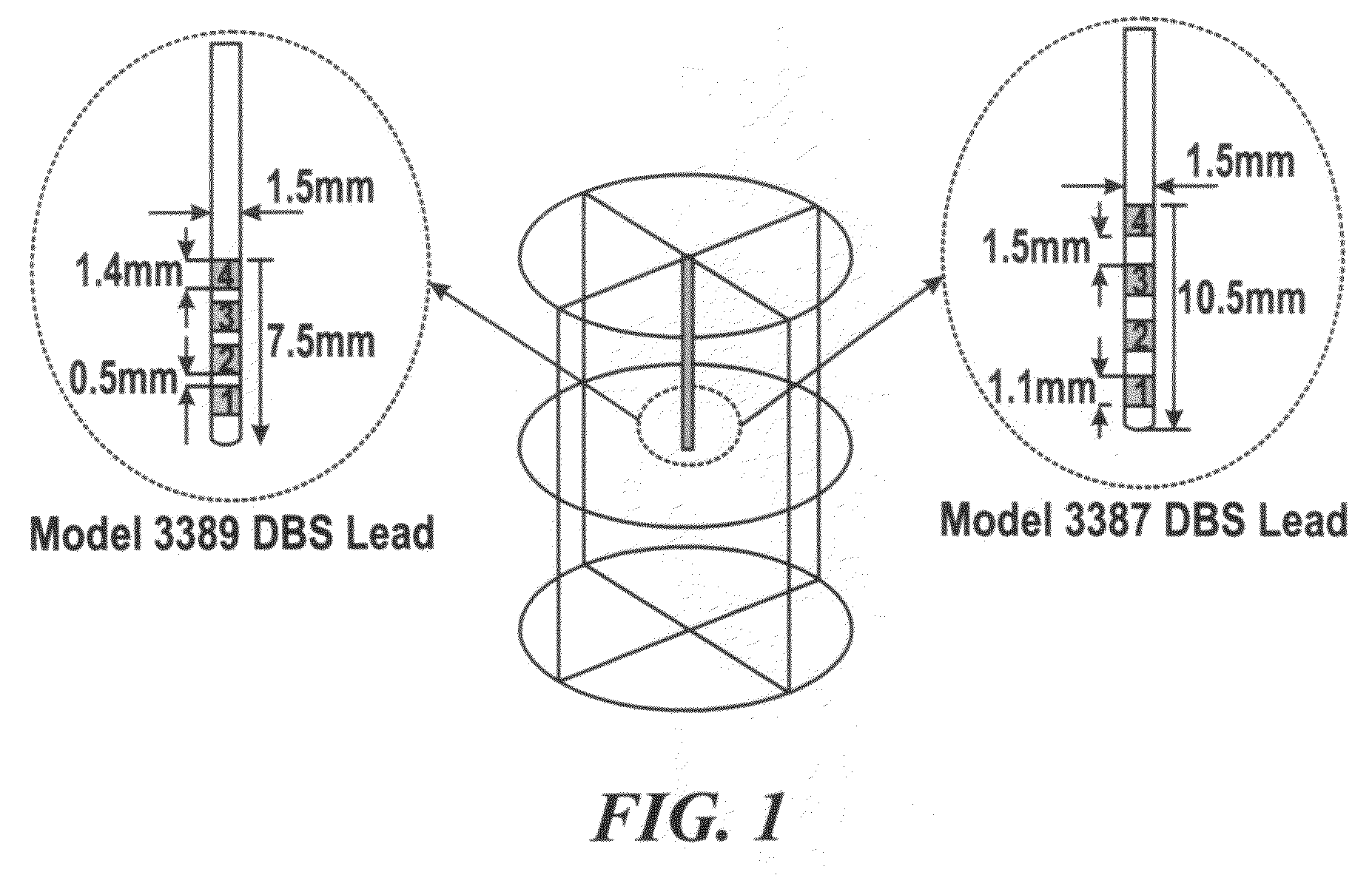
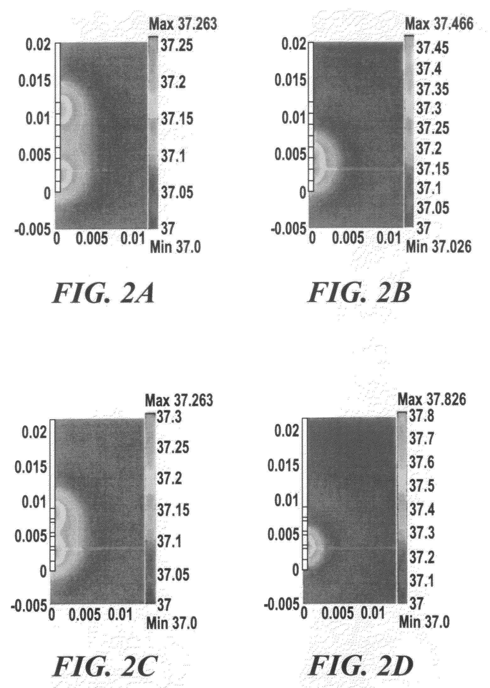
[0123]With Case 1, how the temperature increases solely in response to DBS-induced Joule heat was focused on, without modeling the contribution of blood perfusion or metabolic activity. Therefore, both ωb and Qm are zero. This model also treated the DBS electrode shaft to be electrically and thermally insulated, except that the electrodes 1 and 2—the two electrodes most distal on the DBS lead—were electrically energized.

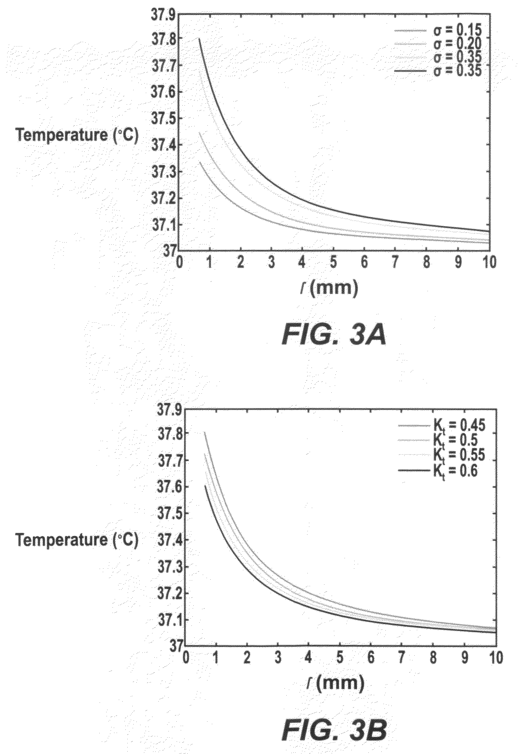
[0124]The temperature distributions using two types of DBS leads—Medtronic DBS Lead 3387 and Lead 3389—were modeled. ‘High setting’ to the two DBS leads was applied and how electrical conductivity and thermal conductivity affected the resulting temperature distribution in the brain tissue was investigated. FIG. 3A and TABLE 1, SECTION I show changes in peak temperature and temperature field distribution as a function of tissue electrical conductivity (σ=0.15 to 0.35 S / m) with thermal conductivity (Kt) fixed at 0.527 W / m.° C. FIG. 3B and TABLE 1, SECTION II show chang...


PUM


Abstract

A method to control tissue/device heating at implantable medical devices including neuroprosthetic devices. In a first embodiment, thermal conductivity of components of the implantable medical devices including the neuroprosthetic devices is increased. In a second embodiment, the implantable medical devices including the neuroprosthetic devices are cooled by using heat-sinks. In a third embodiment, portions of the implantable medical devices including the neuroprosthetic devices are replaced with specific thermal properties. In a fourth embodiment, the implantable medical devices including the neuroprosthetic devices are coated with a drug/material that will induce surrounding tissue to become more resistant to temperature increases. In a fifth embodiment, the temperature increase near the implantable devices including the neuroprosthetic devices is determined using a modified bio-heat transfer model. In a sixth embodiment, the shape of the outer or the inner surface of the device is modified.

Description

THE CROSS REFERENCE TO RELATED APPLICATIONS [0001]The instant nonprovisional patent application is a national patent application claiming priority from PCT international patent application number PCT / US2007 / 018484, filed on 21 Aug. 2007, and entitled METHOD TO REDUCE HEATING AT IMPLANTABLE MEDICAL DEVICES INCLUDING NEUROPROSTHETIC DEVICES, which claims priority from provisional patent application No. 60 / 839,002, filed on Aug. 21, 2006, and entitled METHOD TO REDUCE HEATING AT IMPLANTABLE MEDICAL DEVICES INCLUDING NEUROPROSTHETIC DEVICES, and which are both incorporated herein by reference thereto.THE BACKGROUND OF THE INVENTION [0002]A. The Field of the Invention[0003]The embodiments of the present invention relate to a method to reduce heating or to change spatial distribution of heating, and more particularly, but not by way of limitation, the embodiments of the present invention relate to a method to reduce heating or to change spatial distribution of heating at implantable medic...

Claims


Application Information

Patent Timeline
IPC IPC(8): A61N1/375
CPCA61N1/08A61N1/36082G01R33/31A61N1/375G01R33/288A61N1/3718
Inventor BIKSON, MAROMELWASSIF, MAGED M.KONG, QINGJUN
Owner BIKSON MAROM
Why Eureka
Try Eureka