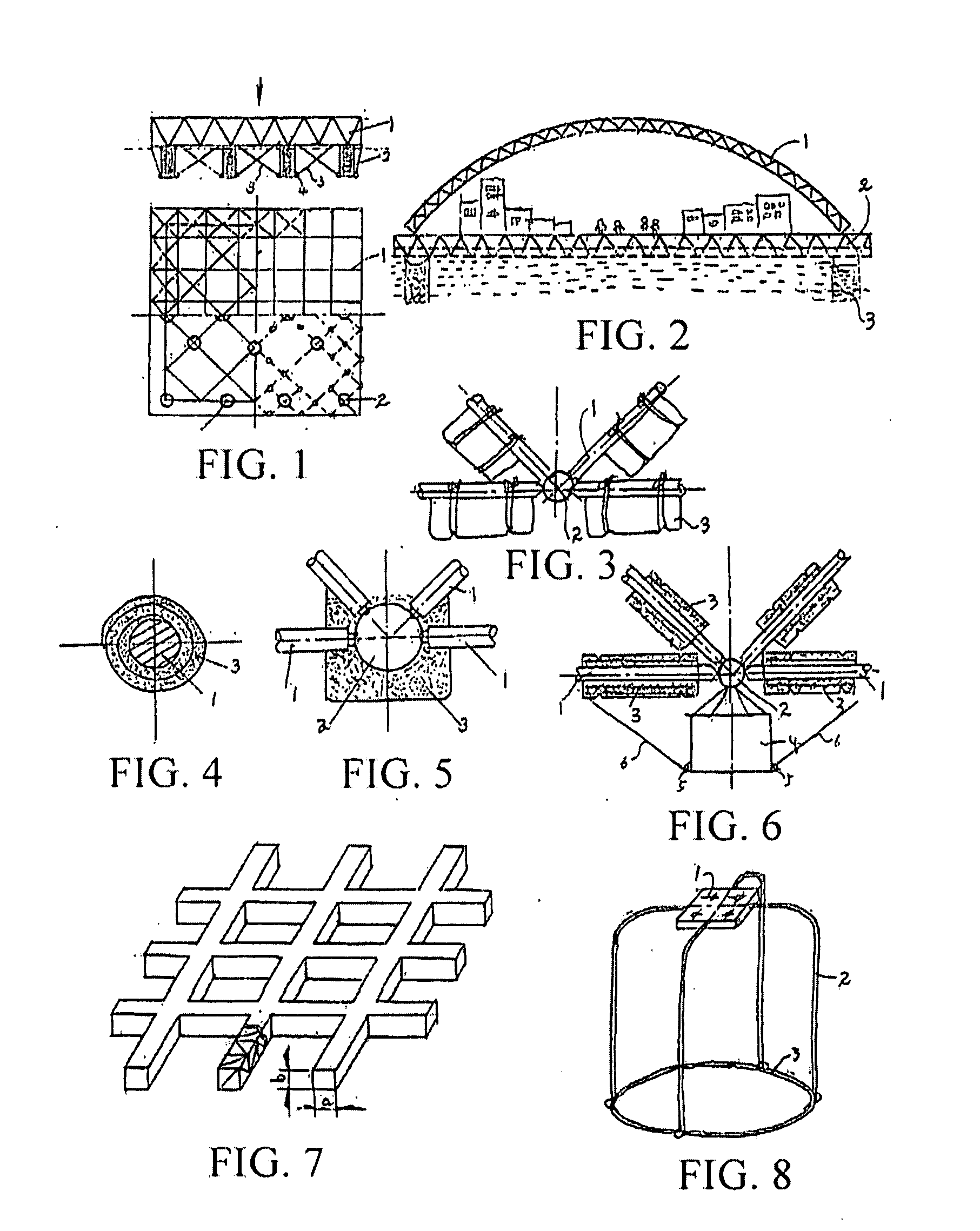
[0025]19. When it is selected that the lower chord joints of the floating grid structure or the floating lattice truss structure are floating members and provided with devices for connecting to rod members, the lower chord joints are variants and are floating members protruding
underwater from the floating grid structure or the floating lattice truss structure assembled thereby. The configuration of variants aims at increasing the volume of the lower chord joints and thus increasing the
buoyant force.
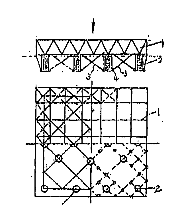
[0031]25. The lower chord joints of the floating grid structure or the floating lattice truss structure are fixedly connected to floating structures, so as to increase the buoyant forces.
[0058]The beneficial effects of the present invention lie in that, through being combined with the floating structure, the lattice structure is capable of being applied above water, and thus has a wider application range. With the same
material consumption, a grid structure, a reticulated shell structure, and a lattice truss structure can cover a relatively large water surface and counteract the influence on the floating structure caused by
waves, since they are spatial structures and have advantages of a
long span, light weight, and high degree of industrialization. In addition, since the grid structure, the reticulated shell structure, and the lattice truss structure have a sufficient rigidity, a floating latticework serving as the floating structure can effectively overcome the torsional moment effect on the floating structure caused by the
waves. When the grid structure or the lattice truss structure is disposed on a plurality of floating structures, or members of the grid structure or the lattice truss structure are respectively combined with floating structures, or the members themselves are floating structures, since the grid structure or the lattice truss structure are spatial structures, various winds and
waves pass through the space thereof, which greatly reduces the influence caused by the waves. In addition, since a plurality of floating structures is distributed at lower chord joints, or floating members constituting the lattice structure are uniformly-distributed to form a plurality of “small water surface profiles” on the water surface and they are uniformly-distributed at wave peaks and valleys below a large covering surface, the increase and decrease of buoyant forces at different positions of the floating structures caused by fluctuation of the waves are counteracted naturally. Therefore, the floating grid structure or lattice truss structure is a fairly stable structure.
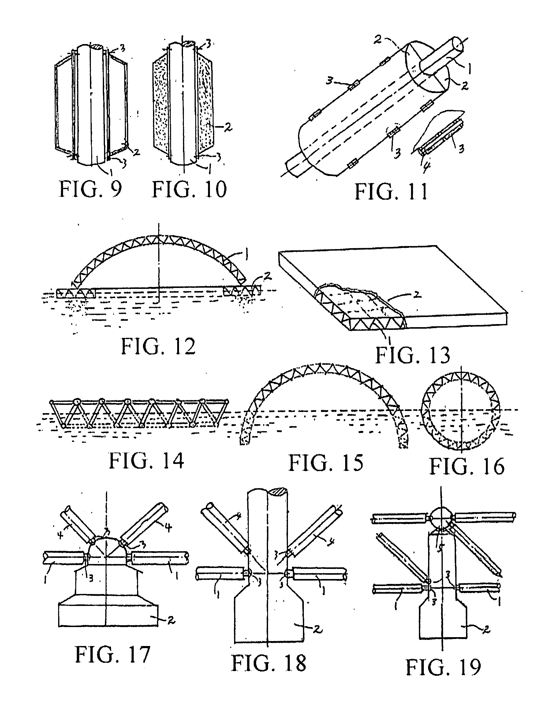
[0059]As compared with the prior art, the present invention exploits a new use of the grid structure, reticulated shell structure, or lattice truss structure. Instead of utilizing a space covered below the structure, the present invention aims at enabling the structure to float above water to form a novel floating structure, in which the structure of the present invention has a
spatial structure, a stable
buoyant force, a desirable rigidity, and is easily assembled to form a very large structure, and when a plate-shaped structure is covered on an upper plane of the structure, the structure of the present invention is used to support objects.
[0064]The floating latticework and floating reticulated shell structure make full use of the sufficient rigidity of the lattice structure. A grid structure or a lattice truss structure is used as skeletons of a box-shaped, flat-plate-shaped, or flat-plate-shaped VLFS, or a liquid cargo ship. A reticulated shell structure is used as skeletons of a ship body structure and a
cofferdam structure to achieve a high rigidity and strength. Especially for very large ships and vary large
cofferdam structures, the sufficient rigidity of the reticulated shell structure can be sufficiently utilized, thus enabling the very large ships to overcome the torsional moment effect on the ship body caused by the waves and enabling the very large cofferdam structure to overcome the huge
water pressure underwater.
[0065]Since the lattice structure is an
assembly structure with a high industrialization degree, when using the floating latticework as a floating structure and using a double-layer reticulated shell structure as a ship body structure, it can improve the industrialization degree of floating structures and ships and further accelerate the shipbuilding process. Moreover, the difficulty for manufacturing very large ships can be reduced, thereby making the manufacturing of VLFSs become much easier.

