Junction box for photovoltaic systems

a photovoltaic system and junction box technology, applied in the direction of pv power plants, electrical apparatus casings/cabinets/drawers, coupling device connections, etc., can solve the problems of complex construction, lack of reliable electrical connections, laborious installation, etc., and achieve reliable physical and electrical connections

Active Publication Date: 2010-09-02
HEYCO
View PDF16 Cites 69 Cited by
  • Summary
  • Abstract
  • Description
  • Claims
  • Application Information

AI Technical Summary

Benefits of technology

[0004]The present invention overcomes the disadvantages and shortcomings of the prior art discussed above by providing a junction box for a photovoltaic system that includes a housing having a base and a cover removably attached thereto. A plurality of guide channels extend from an exterior surface of the housing to an interior portion thereof. The guide channels are sized and shaped to receive a plurality of conductive foil strips from a solar panel array. When the foil strips are fed into the guide channels, they are guided to and properly positioned within corresponding receptacles. Each receptacle is sized and shaped to receive a buss bar. Each foil strip is connected to a corresponding buss bar by a low insertion connector. When the cover is fully engaged with the base, bosses extending from the cover press against the connectors, creating a spring tension, which, in turn, pinches and retains the associated foil strip. As a result, a reliable physical and electrical connection between the foil strips and the buss bars is achieved.

Problems solved by technology

Current junction boxes, however, are complex in construction and installing them can be laborious.
In addition, current junction boxes do not provide reliable electrical connections and their durability is low.

Method used


Image

  • Junction box for photovoltaic systems
  • Junction box for photovoltaic systems
  • Junction box for photovoltaic systems

Examples


Embodiment Construction

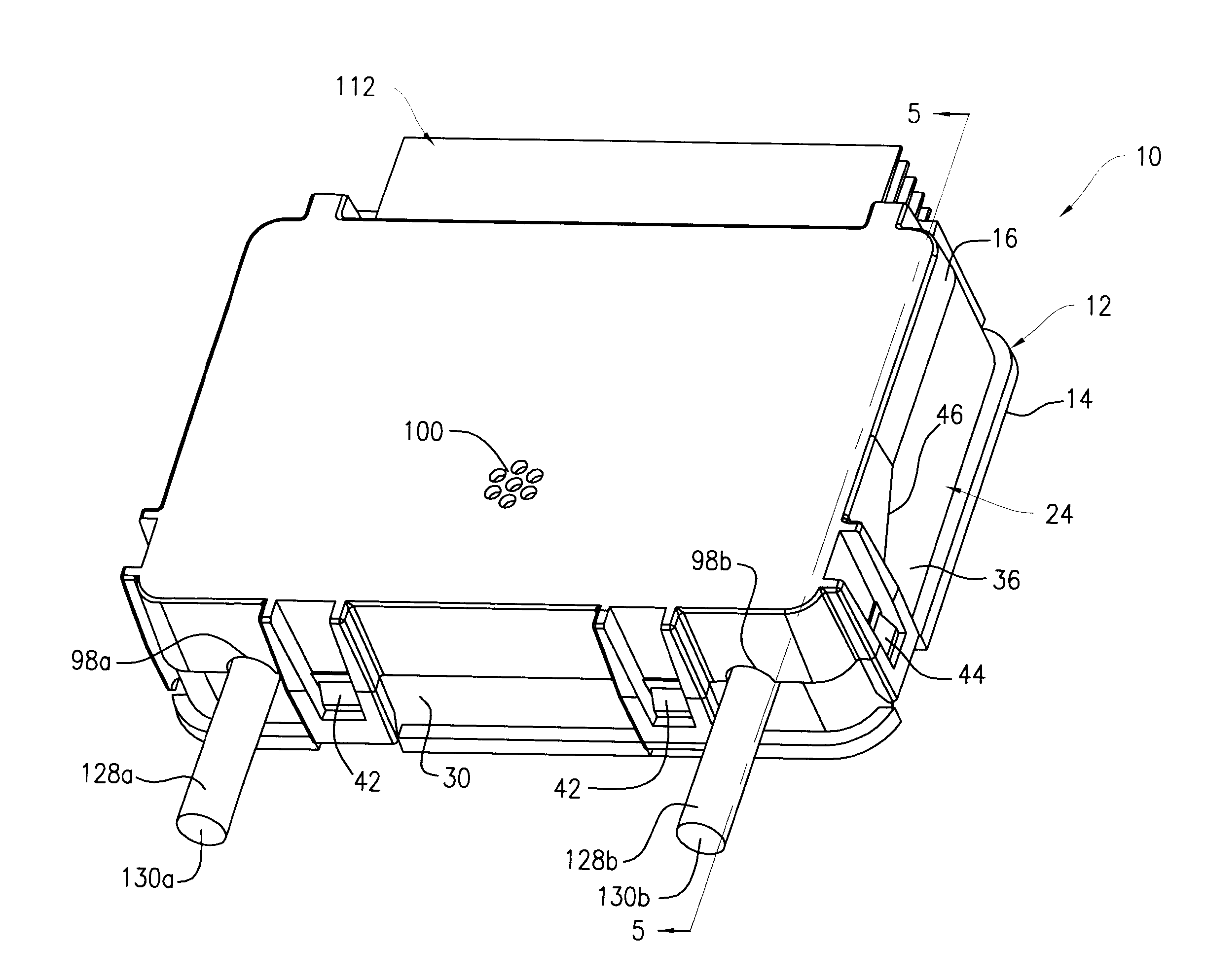
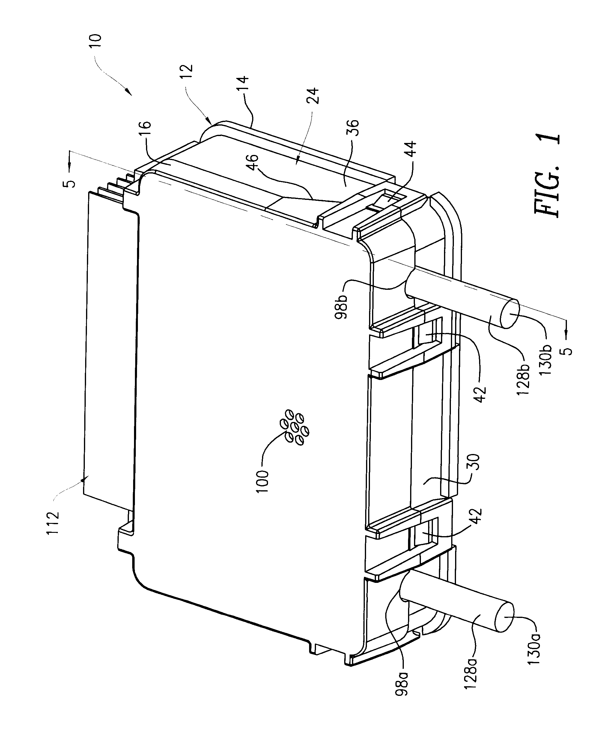
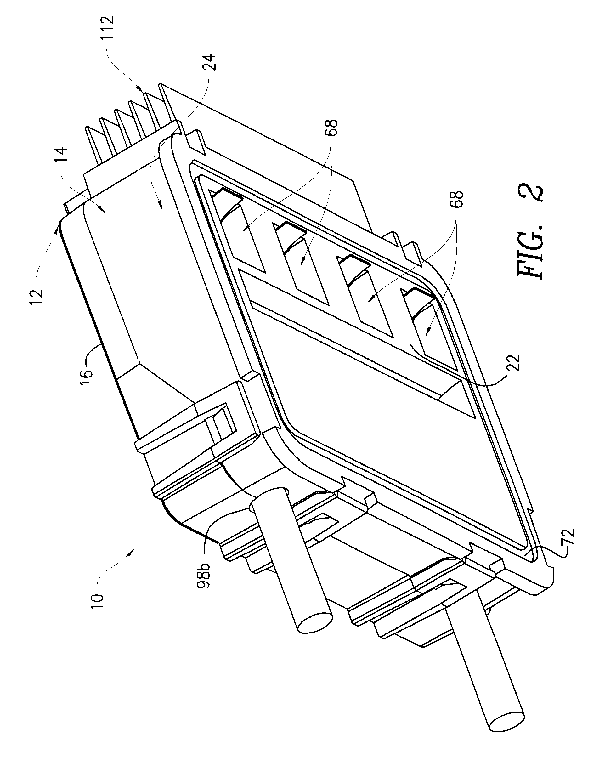
[0016]Referring to FIGS. 1 and 2, an electrical junction box 10 includes a rectangular-shaped housing 12 having a base 14 and a cover 16 attached removably to the base 14. The base 14 and the cover 16 are separate and distinct components, but they may be of unitary construction. The housing 12 is manufactured from a thermoplastic polymer, such as polycarbonate. However, the housing 12 may be manufactured from any other suitable materials known in the art, especially materials having electrical insulating properties. Although the housing 12 is rectangular in shape, it may consist of other shapes and sizes (e.g., square, oblong, circular, elliptical, etc.) in order to accommodate a variety of applications.

[0017]Referring to FIGS. 2 and 3, the base 14 includes a floor 18 having an interior surface 20 and an exterior surface 22 opposite thereof, and a wall 24 that extends outwardly from the floor 18 and around the perimeter thereof. The wall 24 has an interior surface 26 and exterior su...


PUM


Abstract

A junction box for a photovoltaic system includes a housing having a base and a cover removably attached thereto, and a plurality of guide channels extending from an exterior surface of the housing to an interior portion thereof. The guide channels are sized and shaped to receive a plurality of conductive foil strips from a solar panel array. When the strips are fed into the guide channels, they are guided to and properly positioned within corresponding receptacles. Each receptacle is sized and shaped to receive a buss bar, and each strip is connected to a corresponding buss bar by a low insertion connector. When the cover is fully engaged with the base, bosses extending from the cover press against the connectors, creating a spring tension and pinch and retain the associated strip. As a result, a reliable physical and electrical connection between the strips and the buss bars is achieved. A heat sink having a plurality of fins protrude outwardly from the housing to dissipate heat externally.

Description

CROSS-REFERENCE TO RELATED APPLICATION [0001]This application is a Section 111(a) application relating to commonly owned, co-pending U.S. Provisional Application Ser. No. 61 / 092,840 entitled “JUNCTION BOX FOR PHOTOVOLTAIC SYSTEMS” filed Aug. 29, 2008.FIELD OF THE INVENTION[0002]The present invention relates to an electrical junction box and, more particularly, an electrical junction box for use in connection with photovoltaic systems.BACKGROUND OF THE INVENTION[0003]There is a growing need for renewable energy sources, with solar energy being at the forefront. As a result, the use of photovoltaic systems has increased exponentially in recent years. An electrical junction box is an integral part of a photovoltaic system, as it provides electrical connections between individual solar panels (i.e., photovoltaic modules) of a solar array and between the solar panels to other system components (e.g., a DC / AC inverter, etc.). Consequently, the reliability of the junction box is crucial fo...

Claims


Application Information

Patent Timeline
Patent Type & Authority Applications(United States)
IPC IPC(8): H01L31/0203H01R13/46H05K7/20
CPCH01R13/114H01R31/08H02S40/345H02S40/34H05K7/026Y02E10/50
Inventor COYLE, JR., WILLIAM J.GIGLIO, VINCENTJEROME, MICHAELJEROME, THOMAS A.
Owner HEYCO
Why Eureka
Try Eureka