Fast hybrid helicopter with long range and an optimized lift rotor

Active Publication Date: 2010-09-02
EUROCOPTER
View PDF14 Cites 15 Cited by
  • Summary
  • Abstract
  • Description
  • Claims
  • Application Information

AI Technical Summary

Benefits of technology

[0117]It is advantageous to be able to adjust or even reduce to zero the tilting moment of the fuselage, since firstly that acts directly on the bending moment in the rotor mast and thus on the fatigue stress it suffers, and secondly that leads to overall balance of the vehicle resulting from the distribution of power between the propellers and the rotor. This distribution has an influence on the overall power balance, since the propellers and the rotors have respective different efficiencies.
[0118]During this operation, the distribution of power between the rotor and the propellers can vary significantly as a function of the angle of inclination of the rotor disk because of its contribution to variations in total drag and in the propulsion of the vehicle. By way of example, the power needed in high speed cruising flight is due mainly to the parasitic drag of the vehicle. At 140 kt, parasitic drag represents approximately 50% of the total power requirements and can reach 75% at 220 kt, i.e. three times the power needed for lift. Efficiency at high speed thus depends on minimizing parasitic drag.
[0119]The hybrid helicopter is also innovative in that it has first means for controlling, optionally automatically, the angle at which said at least one pitch control surfa

Problems solved by technology

That configuration is not capable of vertical flight unless the rotor is initially set into rotation by an auxiliary device enabling the rotor to be caused to rotate faster: an autogyro is therefore not capable of performing hovering flight but only of moving upwards or downwards on flightpaths having very steep slopes.
Of those various kinds of rotorcraft, the helicopter is the simplest, and as a result it has been successful in spite of having a maximum horizontal speed in translation of about 300 kilometers per hour (km/h) which is small and less than that which can be envisaged by compound and convertible type formulae that are technically more complex and more expensive.
Under such conditions, improvements to the above formulae have been proposed for increasing rotorcraft per

Method used


Image

  • Fast hybrid helicopter with long range and an optimized lift rotor
  • Fast hybrid helicopter with long range and an optimized lift rotor
  • Fast hybrid helicopter with long range and an optimized lift rotor

Examples


Example

[0148]Elements present in two or more distinct figures are given the same reference in each of them.

MORE DETAILED DESCRIPTION

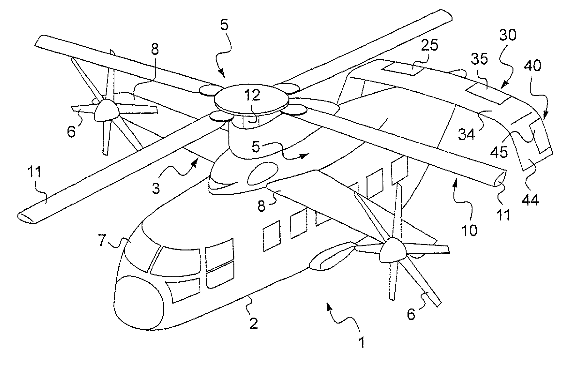
[0149]In FIG. 1, there can be seen a hybrid helicopter 1 made in accordance with the invention.

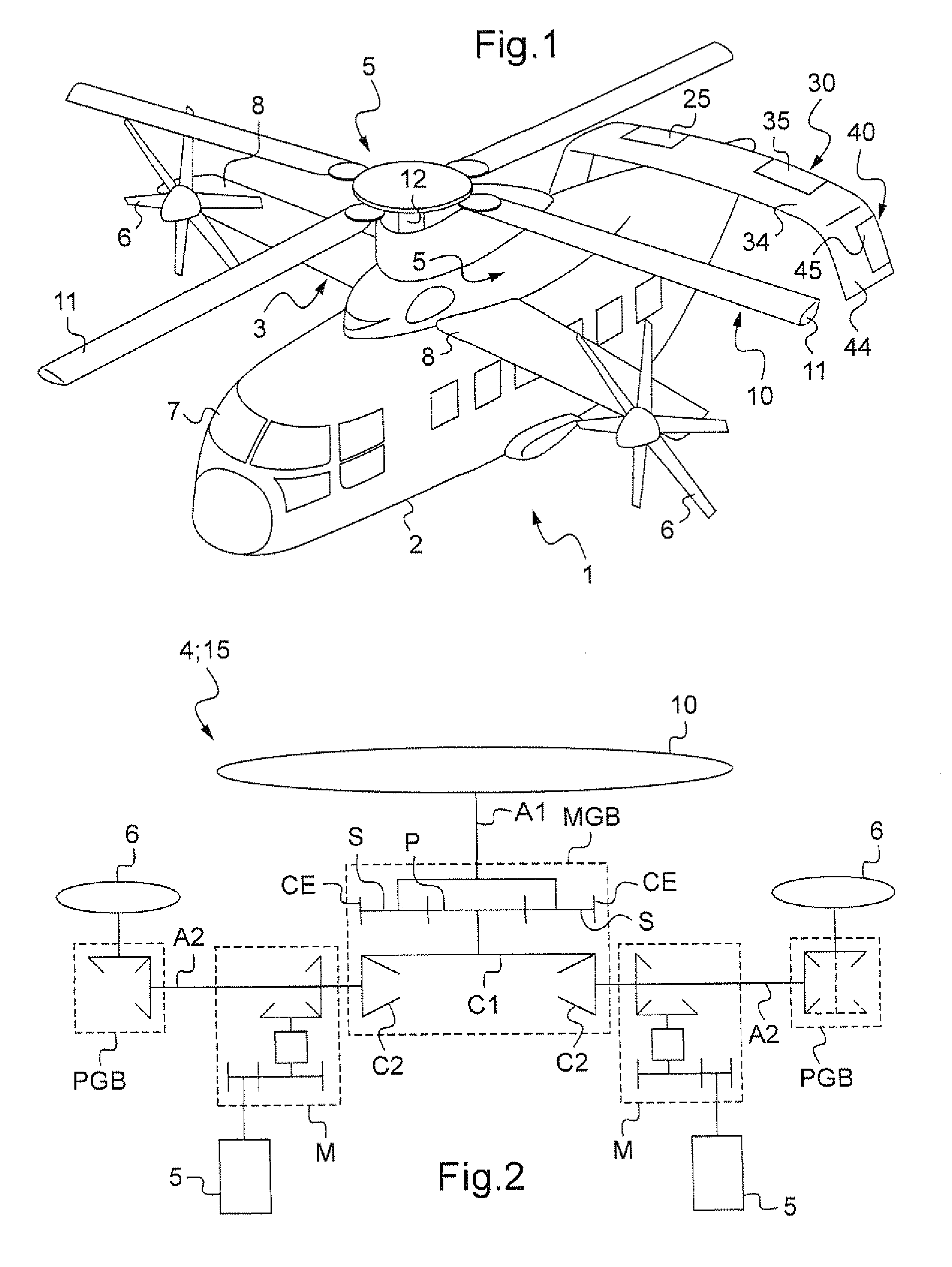
[0150]In the usual way, the hybrid helicopter 1 comprises a fuselage 2 with a cockpit 7 at the front thereof, a rotor 10 for driving blades 11 in rotation by means firstly of two turbine engines 5 disposed on top of the fuselage 2 (not visible in FIG. 1 because of the presence of fairing), on either side of the longitudinal plane of symmetry of the rotorcraft, and secondly a main first gearbox MGB (not shown in FIG. 1).

[0151]Furthermore, the hybrid helicopter 1 is provided with a high wing 3 made up of two half-wings 8 disposed on top of the fuselage 2, these half-wings 8 being substantially rectangular in plane view and presenting a negative dihedral angle.

[0152]The hybrid helicopter 1 is propelled by two propellers 6 driven by the two turbine engines 5, one propell...


PUM


Abstract

A hybrid helicopter (1) includes firstly an airframe provided with a fuselage (2) and a lift-producing surface (3), together with stabilizer surfaces (30, 35, 40), and secondly with a drive system including:
    • a mechanical interconnection system (15) between firstly a rotor (10) of radius (R) with collective pitch and cyclic pitch control of the blades (11) of the rotor (10), and secondly at least one propeller (6) with collective pitch control of the blades of the propeller (6); and
    • at least one turbine engine (5) driving the mechanical interconnection system (15). The speed of rotation (Ω) of the rotor (10) is equal to a first speed of rotation (Ω1) up to a first flightpath air speed (V1) of the hybrid helicopter (1), and is then reduced progressively in application of a linear relationship as a function of the flightpath air speed of the hybrid helicopter.

Description

[0001]The present invention relates to a rotorcraft with long range and a high forward speed in cruising flight due to an optimized lift rotor.BACKGROUND OF THE INVENTION[0002]More particularly, the invention relates to a hybrid helicopter relating to an advanced concept for a vertical takeoff and landing aircraft (VTOL).[0003]This advanced concept combines, at reasonable cost, the efficiency in vertical flight of a conventional helicopter with the high travel speed performance made possible by installing modern turbine engines.[0004]In order to understand clearly the object of the invention, it is appropriate to recall the main heavier-than-air craft correspond to airplanes and to rotorcraft.[0005]The term “rotorcraft” is used to designate any vehicle in which all or some of its lift is provided by one or more propellers of substantially vertical axis and large diameter, referred to as rotors or as rotary wings.[0006]There are several distinct types in category of rotorcraft.[0007]...

Claims


Application Information

Patent Timeline
IPC IPC(8): B64C27/26
CPCB64C2027/8281B64C27/26
Inventor ROESCH, PHILIPPE
Owner EUROCOPTER
Why Eureka
Try Eureka