Optical module and process for manufacturing the same

a technology of optical modules and manufacturing processes, applied in the field of optical modules, can solve the problems of insufficient bonding strength and difficulty in allowing a lens-containing optically-transmitting member to be absorbed, and achieve the effect of easy adhesion to the receptacl

Inactive Publication Date: 2010-09-02
RENESAS ELECTRONICS CORP
View PDF4 Cites 7 Cited by
  • Summary
  • Abstract
  • Description
  • Claims
  • Application Information

AI Technical Summary

Benefits of technology

[0019]According to the present invention, the lens-containing optically-tran

Problems solved by technology

H4-243,179 may exhibit insufficient bonding strength, due to a difficulty in the injection of or the coating with the adhesive agent.
As described above, it is di

Method used


Image

  • Optical module and process for manufacturing the same
  • Optical module and process for manufacturing the same
  • Optical module and process for manufacturing the same

Examples


first embodiment

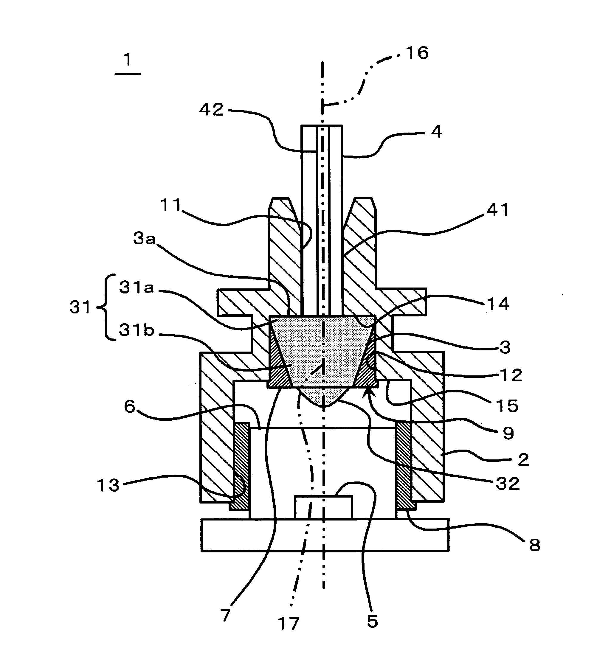
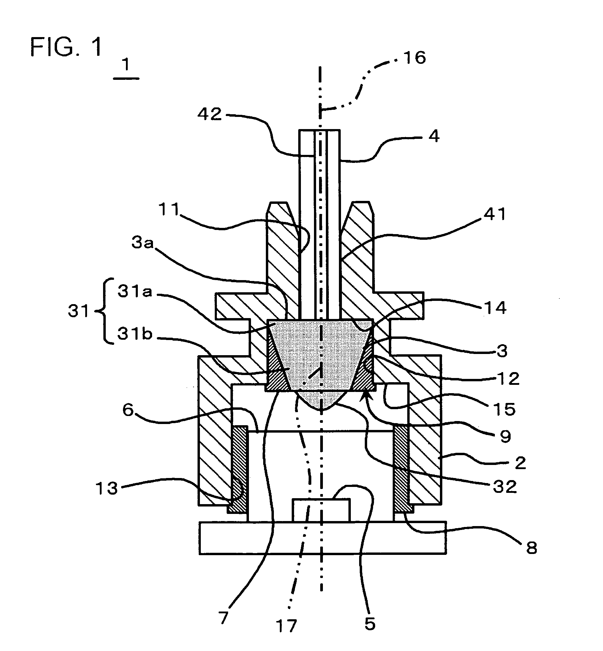
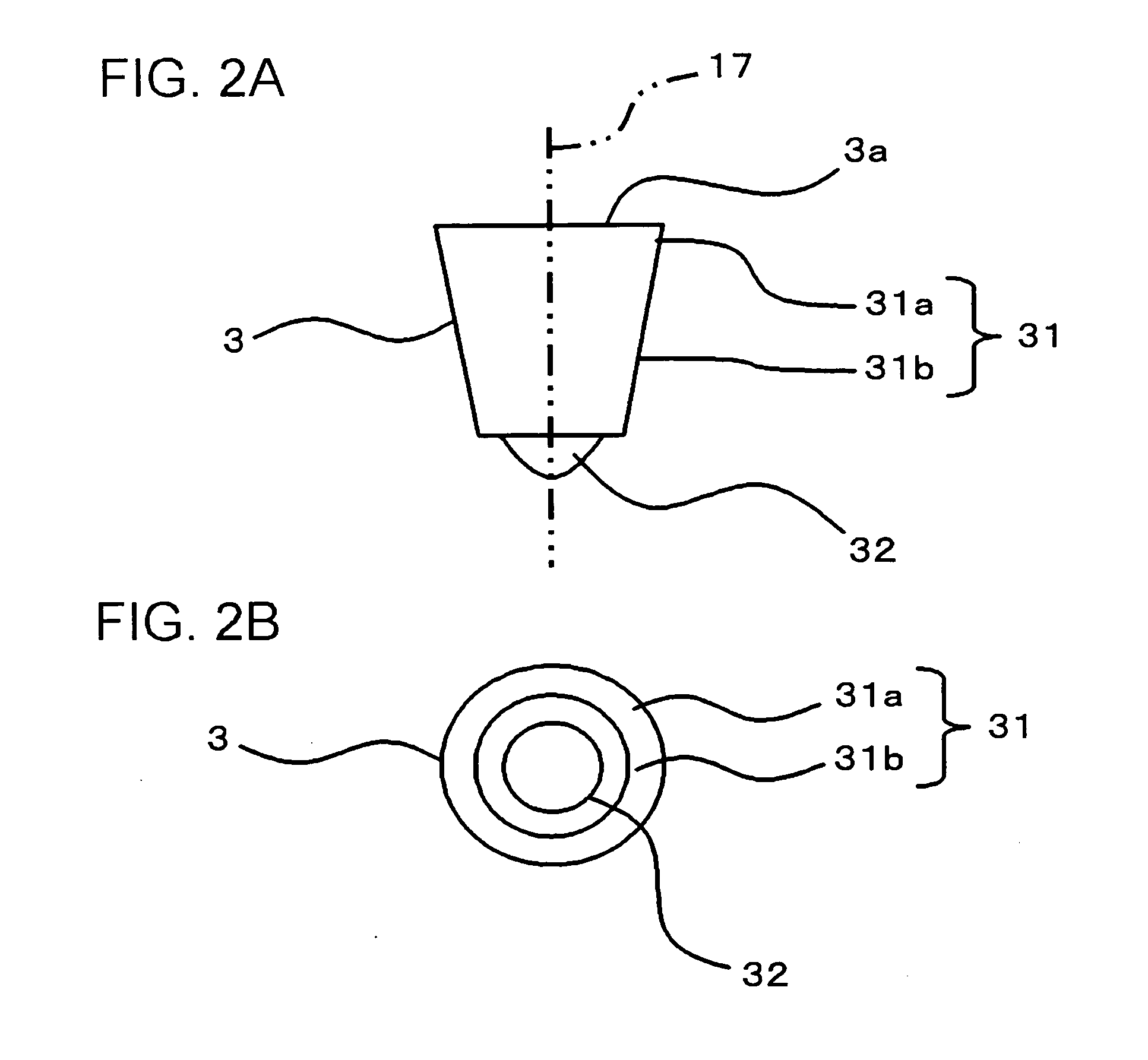
[0034]FIG. 1 is a cross-sectional view, illustrating a configuration of an optical module 1 according to first embodiment, and in particular, a diagram illustrating a condition having an optical connector 4 inserted therein. FIG. 2A is a front view, illustrating a configuration of a glass containing lens 3 of the optical module 1, and FIG. 2B is a bottom view of the glass containing lens 3 from the underside. FIG. 3 is a cross-sectional view, illustrating an example of an operation for fixing the glass containing lens 3 to the receptacle 2 of the optical module 1.

[0035]The optical module 1 according to the present embodiment includes a lens-containing optically-transmissive member (for example, glass containing lens 3) and a receptacle 2. The receptacle 2 includes: an optical connector-inserting section 11, in which the optical connector 4 is inserted; a fixing section for fixing the lens-containing optically-transmissive member (for example, a fixing section 12 for fixing the glass...

second embodiment

[0069]FIG. 4A is a front view of a glass containing lens of the optical module according to the embodiment, and FIG. 4B is a bottom view thereof (diagram for showing the whole module is not presented).

[0070]An optical module according to the present embodiment has similar configuration as employed in the optical module 1 of first embodiment, except that the optical module includes a glass containing lens 60 of FIG. 4A in place of the glass containing lens 3 of the optical module 1 according to the above-described first embodiment. Further, the fixing section 12 of the optical module according to the present embodiment is formed to be a square pole in accordance with the shape of the glass containing lens 60. The optical module according to the present embodiment is configured to have similar configuration as the optical module 1 according to the above-described first embodiment in other aspects.

[0071]As shown in FIGS. 4A and 4B, the glass containing lens 60 includes a main body 61 a...


PUM

PropertyMeasurementUnit
Diameteraaaaaaaaaa

Abstract

An optical module includes a lens-containing optically-transmissive member and a receptacle. The receptacle includes: an optical connector-inserting section; a fixing section for fixing the member; and an device-installing section for installing a semiconductor device serving as a light emitting device or a light receiving device. The fixing section communicates with the device-installing section. The member includes a main body and a lens. The main body includes a first section and a second section, the first section having a first outer diameter, which is substantially equal to a internal diameter of said fixing section, and said second section having a second outer diameter, which is smaller than the first outer diameter, and at least containing an end of said main body in a side of the device-installing section.

Description

[0001]This application is based on Japanese patent application No. 2009-22,384, the content of which is incorporated hereinto by reference.BACKGROUND[0002]1. Technical Field[0003]The present invention relates to an optical module and a process for manufacturing thereof.[0004]2. Related Art[0005]Optical modules for coaxial transmission or reception installed in an optical transceiver such as 10 Gb / s small form-factor pluggable (XFP) transceiver and the like are classified to optical modules for telecom (phone-related) applications utilized for communication distance of 10 kilometers (km) to 40 kilometers and optical modules for datacom (data communication) applications utilized for communication distance of 220 meters (m) to 10 km.[0006]Such types of optical modules for coaxial transmission or reception applications are typically disclosed in, for example, Japanese Patent Laid-Open No. H4-243,179 (1992). FIG. 9 is a cross-sectional view, illustrating a configuration of an optical mod...

Claims


Application Information

Patent Timeline
IPC IPC(8): G02B6/32B29C65/52
CPCG02B6/4204G02B6/4292G02B6/4239G02B6/4244
Inventor MITAMURA, KAZUHIROYAMADA, HIDEYUKI
Owner RENESAS ELECTRONICS CORP
Why Eureka
Try Eureka