Lathe for manufacturing ophthalmic lenses made of plastic

a technology of ophthalmic lenses and lathes, which is applied in the field of turning machines, can solve the problems of affecting the precision of the cutting or turning process of the spectacle lens surface, the size of the primary and secondary components is relatively high, and the tool or its drive constantly induces vibration into the machine bed, so as to achieve the effect of low floor load and low overall mass of the turning and cutting machin

Active Publication Date: 2010-09-09
SCHNEIDER GMBH & CO KG
View PDF5 Cites 12 Cited by
  • Summary
  • Abstract
  • Description
  • Claims
  • Application Information

AI Technical Summary

Benefits of technology

[0047]Ultimately, it is advantageous when in the functional embodiment, an overall mass with the maximum value m3 is specified, wherein the value m3 lies between 500 kg and 1000 kg, between 600 kg and 800 kg, between 670 kg and 780 kg or 750 kg. With the design of the machine bed according to the invention, a lower overall mass of the turning and cutting machine can be achieved. This extends the possible use of the machine in areas with a relatively low floor load.

Problems solved by technology

However, the size of the primary and secondary components entails a relatively high weight.
The turning tool or its drive constantly induce vibrations into the machine bed due to the high frequency oscillation movement, which have a negative effect on the precision of the cutting or turning process of the spectacle lens surface.
Due to the differently sized lever arms, the forces on the respective force contact point generate different moments in different directions, which cause a corresponding deformation of the machine bed.

Method used


Image

  • Lathe for manufacturing ophthalmic lenses made of plastic
  • Lathe for manufacturing ophthalmic lenses made of plastic
  • Lathe for manufacturing ophthalmic lenses made of plastic

Examples


Embodiment Construction

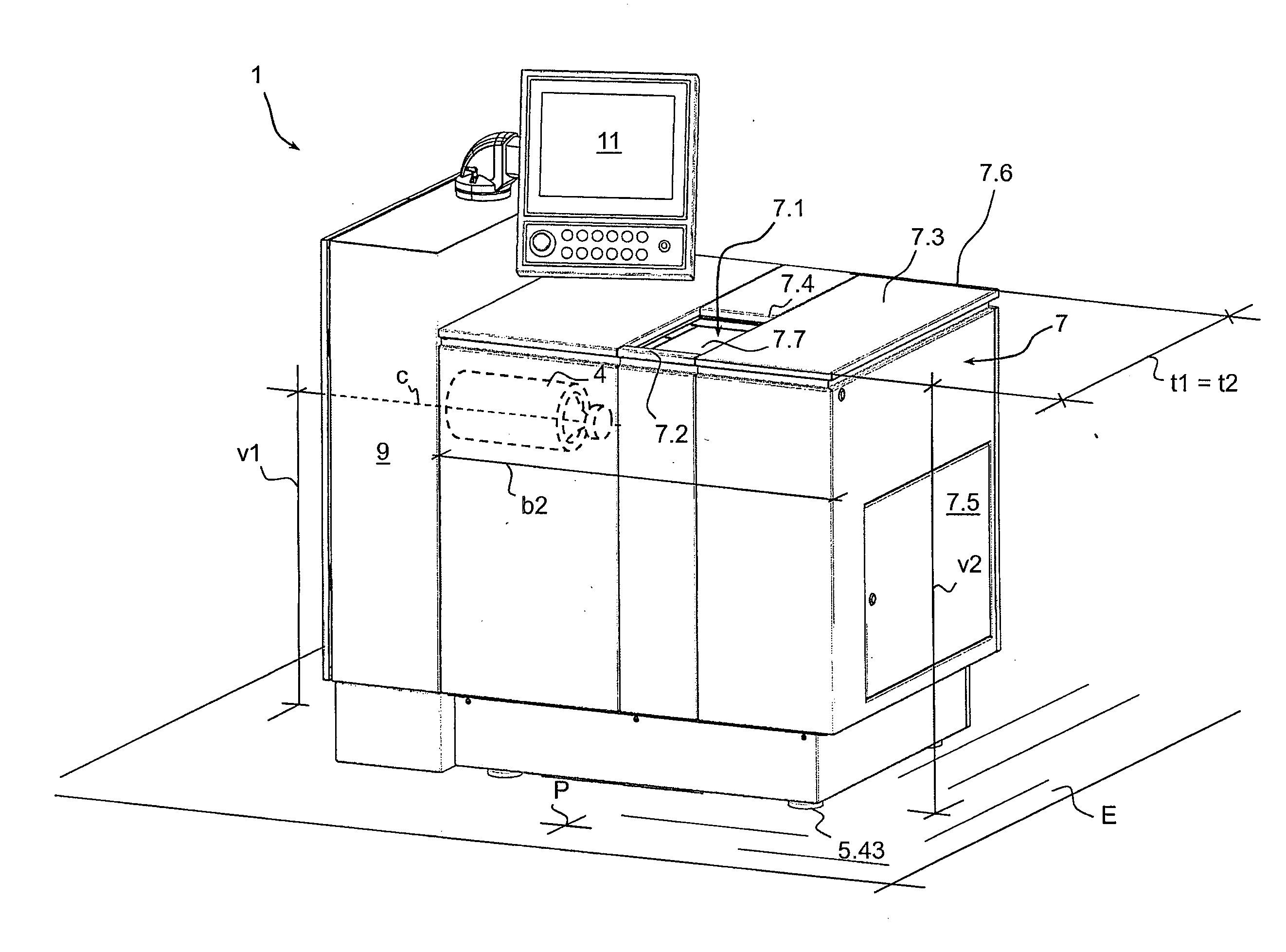
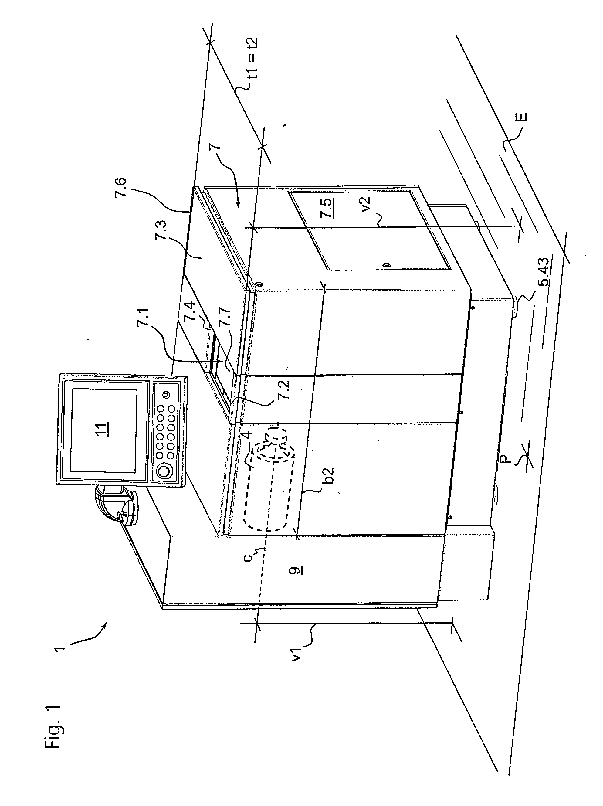
[0060]The turning and cutting machine 1 shown in FIG. 1 comprises a paneling 7 on all sides, which on a right-hand side has a maintenance flap 7.5 and which is limited above by a lid 7.3. The lid 7.3 comprises a recess 7.4 for an access opening 7.1. With regard to an operator position P, a switch cabinet 9 is provided on the left-hand side of the turning and cutting machine 1, on which an operating panel 11 is arranged in such a manner that it can be pivoted. The switch cabinet 9 is here higher than the paneling 7, or the paneling lid 7.3. The lid 7.3 is joined in the area of a rear edge 7.6 in such a manner that it can be pivoted, and is to be folded open upwards by the operator in the position P. For this purpose, the operating panel 11 should be pivoted towards the left-hand side in advance.

[0061]In the folded open state of the lid 7.3 (not shown), the turning and cutting machine 1 is freely accessible from above; in particular in the folded open state of the lid 7.3, all drives ...


PUM

PropertyMeasurementUnit
massaaaaaaaaaa
massaaaaaaaaaa
vertical displacementaaaaaaaaaa

Abstract

A turning machine for producing non rotationally symmetric surfaces of synthetic spectacle lenses, having a support plane E, a machine bed made of cast iron with a width b1 and a mass m1, a linear motor with an actuator comprising a turning tool holder and an oscillation axis Z, a workpiece spindle with a rotational axis C and a movement axis X, wherein the machine bed has at least two bearing surfaces arranged at a distance for the linear motor and for the workpiece spindle, and between the two bearing surfaces, a chip space is provided which is limited at least partially by the machine bed, wherein the linear motor is supported on the first bearing surface and the workpiece spindle is supported on the second bearing surface in relation to the chip space opposite the linear motor, wherein the mass of the machine bed has the maximum value m1, and the value m1 lies between 100 kg and 500 kg, between 150 kg and 300 kg, between 170 kg and 200 kg or 180 kg. A turning machine, in which the ratio of the mass m1 of the machine bed to a moved mass m2 of the linear motor 3 is greater than a quotient Q, wherein the quotient Q is between 1:500 and 1:20, between 1:60 and 1:30 or between 1:140 and 1:100, or 1:40 or 1:120.

Description

FIELD OF THE INVENTION[0001]The invention relates to a turning machine for producing non rotationally symmetric surfaces of synthetic spectacle lenses, comprising a support plane, a machine bed, preferably made of cast iron with a width b1 and a mass m1, a linear motor with an actuator comprising a turning tool holder and an oscillation axis Z, a workpiece spindle with a rotational axis C and a movement axis X, wherein the machine bed comprises at least two bearing surfaces arranged at a distance for the linear motor and for the workpiece spindle, and between the two bearing surfaces, a chip space is provided which is limited at least partially by the machine bed, wherein the linear motor is supported on the first bearing surface and the workpiece spindle is supported on the second bearing surface in relation to the chip space opposite the linear motor.BACKGROUND OF THE INVENTION[0002]The part of the turning machine is referred to as the machine bed which for the purpose of supporti...

Claims


Application Information

Patent Timeline
Patent Type & Authority Applications(United States)
IPC IPC(8): B23B5/00B23B17/00
CPCB23Q1/015B23Q11/0035Y10T82/2566Y10T82/2585Y10T82/2595B23Q2230/004
Inventor SCHNEIDER, GUNTERBUCHENAUER, HELWIGBORNER, ULFKRAMER, KLAUS
Owner SCHNEIDER GMBH & CO KG
Why Eureka
Try Eureka