
Fuel Leak Prevention System

a technology of fuel leak prevention and fuel injection, which is applied in the direction of liquid transferring device, liquid handling, packaging goods type, etc., can solve the problems of fire, environmental hazard, environmental damage,

Inactive Publication Date: 2010-09-09
STRICTLY GREEN
View PDF11 Cites 9 Cited by
  • Summary
  • Abstract
  • Description
  • Claims
  • Application Information

AI Technical Summary

Benefits of technology

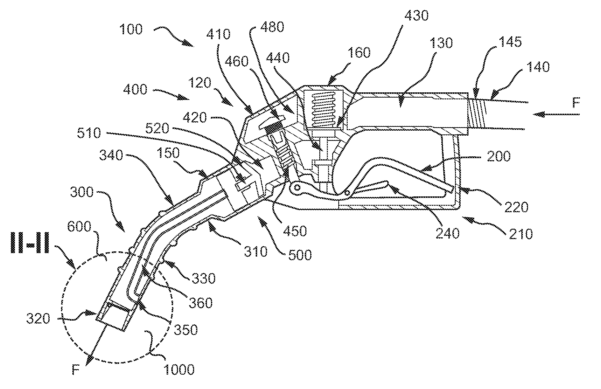
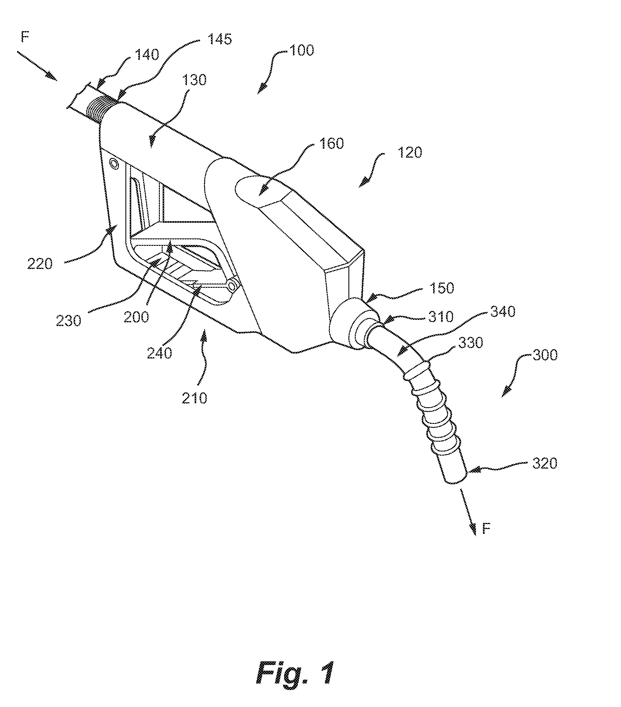
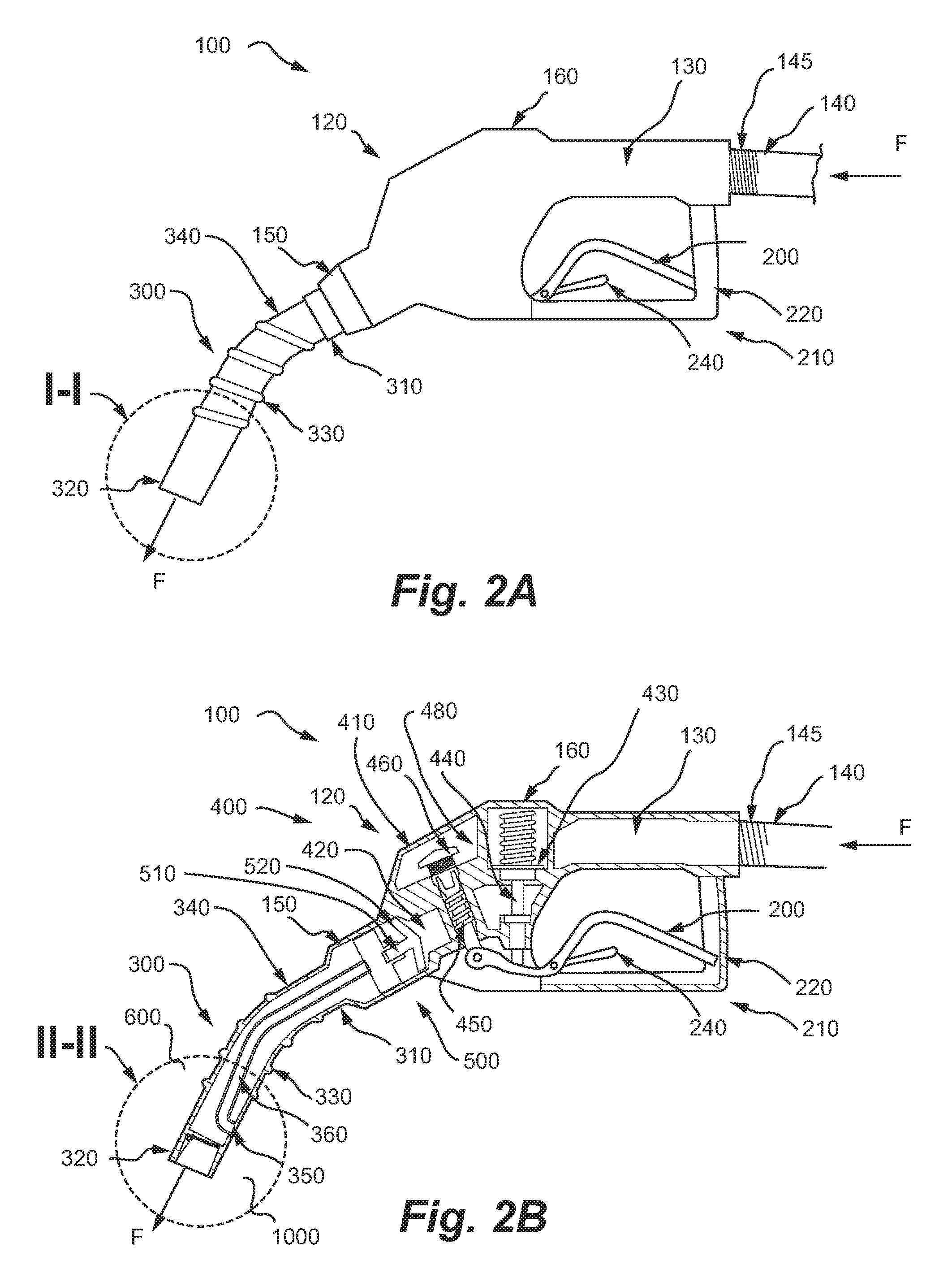
[0020]Briefly described, in preferred form, the present invention is a fuel leak prevention system that comprises a check valve insert comprising a pivoting flap that is preferably spring-loaded and located in proximity to the dispensing end of the spout of a fuel dispensing nozzle. The check valve insert prevents the flow of fuel at the terminal end of the spout. By stopping the flow of fuel in proximity to terminal end of the nozzle (as opposed to at a location interior to the nozzle, e.g., the poppet valve stem in the handle of the nozzle), there is no drippage of the fuel that remains in the spout after the nozzle has been deactivated. The check valve insert is positionable in proximity to the outlet end of the fuel dispensing nozzle. In one embodiment, the check valve can be inserted into the spout during fabrication of the nozzle. An alternate embodiment allows the retrofit of an existing nozzle by adding an extension that contains the check valve to the spout on the nozzle.
[0026]In another exemplary embodiment, the present invention can be a method for preventing leakage from an outlet end of a liquid dispensing nozzle, comprising providing a nozzle in fluid communication with a liquid dispensing pump, the nozzle including a body portion, a spout assembly extending from the body portion, and a flow control valve in the body portion operable to allow or prevent the flow of liquid through a flow passage defined by the body portion, wherein the spout assembly has an outlet end configured for dispensing the liquid, and providing a check valve positioned in the outer end of the spout and being responsive to the flow of liquid through the body portion and into the spout and being biasedly disposed to remain closed when no liquid is flowing through the nozzle so as to prevent liquid from dripping when the nozzle is not activated, the check valve comprising a flap member being pivotably attached within the outer end of the spout, and a closing member, preferably a spring, mounted within the outer end of the spout and oriented to engage the flap member by applying a closing force to the flap member sufficient to seat the flap member when the nozzle is not activated, and to allow the flap member to rotate to substantially open the spout and allow the flow of liquid when the nozzle is activated.

Problems solved by technology

When either the hold-open latch is disengaged, or when the anti-drain valve is covered by fuel (full tank) air intake ceases, and the poppet valve stem closes, disrupting the flow of fuel.
This uncontained fuel can be spilled on the car, ground, or on the body, creating a fire, clean-up, and environmental hazard.
In such a nozzle, it is sometimes desirable to provide for a shut-off valve at the tip of the nozzle spout and in the fuel supply passage to avoid drips from the spout after the nozzle is removed from the fill tube of a fuel tank of the motor vehicle, as there is ever increasing concern about damage to the environment resulting from the contamination of ground water and soil due to spillage of vehicle fuels, petroleum substances and other chemicals.
Part of the damage is caused by the dripping of excess liquid from the nozzle used to dispense the fuel or liquid, after the nozzle has been deactivated.
In addition, part of the damage is caused by activation of the nozzle when the nozzle is removed from the container or fuel tank.
Activation of a nozzle outside of a container or fuel tank also presents a safety problem due to the spillage of the flammable fuel.
The wasted fuel may eventually enter a storm drain through run off and cleaning procedures.
Fuel seeping into the ground contaminates soil, streams, rivers, lakes, and drinking water.
For example, one quart of spilled fuel can contaminate 250,000 gallons of fresh drinking water.
One pint of fuel seeping into a lake can create a one acre slick, preventing the replenishment of oxygen, blocking sunlight, and impairing photosynthetic processes.
Spilled fuel also releases Volatile Organic Compounds (VOC's) that have long and short term adverse health effects.
These vapors contribute to air pollution and greenhouse gases.
Over many spills, this can amount to a large amount of fuel inventory lost.
There is also, of course, the considerable inconvenience and potential safety hazards this problem poses to the consumer, including the risk of spillage or drippage onto clothes, shoes, or hands, not to mention the safety hazards posed by drippage of fuel onto the driveways at fueling stations.

Method used


Image

  • Fuel Leak Prevention System
  • Fuel Leak Prevention System
  • Fuel Leak Prevention System

Examples


first exemplary embodiment

[0070]Fuel Leak Prevention System, First Exemplary Embodiment

[0071]In a first exemplary embodiment of the fuel leak prevention system 1000 of the present invention, the nozzle 100 is also conventional and operates as described thus far. An embodiment of the assembled system is depicted in FIGS. 4A, 4B. This embodiment of the fuel leak prevention system 1000 incorporates a check valve insert that comprises a flapper valve 700, a closing member, preferably a spring 800, and a hinge pin 900 combined to function as a spring-loaded pivoting flap, which can be preferably inserted into the dispensing end 320 of the spout 340 of a fuel dispensing nozzle 100 and thus is generally circular shaped so as to fit within the inner diameter of the spout 340 (FIG. 4A). In this embodiment, the closing member is depicted as a rotational spring member 800, which rotates about the longitudinal axis of the hinge pin 900 and is configured to be in constant communication with the flapper valve 700 to apply...

second exemplary embodiment

[0087]Fuel Leak Prevention System, Second Exemplary Embodiment

[0088]In another exemplary embodiment of the fuel leak prevention system 1000 of the present invention, the nozzle 100 is also conventional and operates as described thus far. However, to allow existing nozzles to be retrofitted or refurbished, without replacement, the check valve insert can be a tabular insert or it can be press fit into the end 320 of the spout 340. Also, a removable spout extension 980 that is not provided to the nozzle 100 during manufacturing can be added to an existing nozzle 100 as described below. The spout extension 980 would preferably have a cross-section and external dimensions similar to that of the existing spout 340 so that the outer end 985 of the spout extension 980 can be easily inserted into a fill pipe of a fuel tank or storage container.

[0089]In this embodiment, the check valve insert of the present invention can be inserted into the outer end 985 of the spout extension 980 in a manne...


PUM

PropertyMeasurementUnit
Forceaaaaaaaaaa
Flow rateaaaaaaaaaa
Elastomericaaaaaaaaaa

Abstract

A fuel leak prevention system and method for providing same includes a check valve for insertion into the discharge end of a spout assembly of a fuel dispensing nozzle, the check valve being located downstream of the nozzle's fuel control valve so as to prevent any leaking or dripping of fuel from the spout when the nozzle is deactivated. The check valve includes a pivoting flap that is preferably spring-loaded and predisposed to remain closed to seal the spout when there is no fuel flowing through the nozzle, but which is allowed to rotate within the spout to open the nozzle and allow the flow of fuel when the nozzle is activated. In one embodiment, the check valve can be inserted into the spout during fabrication of the nozzle. An alternate embodiment allows the retrofit of an existing nozzle by adding an extension that contains the check valve to the spout on the nozzle. The system and method disclosed has application to any liquids that are to be dispensed, including petrol, diesel, kerosene, gas oil, gas, liquid petroleum gas, av-gas, chemicals, and water.

Description

CROSS REFERENCE TO RELATED APPLICATION AND PRIORITY CLAIM[0001]This application is a continuation in part of U.S. Non-Provisional patent application Ser. No. 12 / 580,678, filed 16 Oct. 2009, which application claims the benefit of U.S. Provisional Patent Application Ser. No. 61 / 106,195, filed 17 Oct. 2008. Each of the above-listed applications is herein incorporated by reference as if fully set forth below in their entireties.BACKGROUND OF THE INVENTION [0002]1. Field of the Invention[0003]Embodiments of the present invention relate generally to a fuel leak prevention system, and more particularly to a system to prevent fuel from leaking or dripping from the dispensing end of a fuel nozzle after the nozzle has been deactivated.[0004]2. Description of Related Art[0005]Fuel dispensing nozzles of the general type used on fuel pumps in fueling stations are well understood in the art. These nozzles are normally provided with hold-open catches for holding an operating lever in an open posi...

Claims


Application Information

Patent Timeline
IPC IPC(8): B67D7/52
CPCB67D7/52F16K23/00F16K15/033
Inventor BURRIS, STEVEN Y.STRICKLAND, DAVID MICHAELJONES, WILSON A.
Owner STRICTLY GREEN
Learn More