[0018]The method according to the invention can advantageously be combined with known layout
processing methods performed by known layout
processing tools. Typically the known layout
processing tools must be adapted to be able to perform the method according to the invention. However, this combination of the method according to the invention and known layout processing methods enable a further reduction of the processing time. During the known layout processing methods the objects of the
integrated circuit layout must be scanned after which compliance with the set of design-rules is checked. When combining the method according to the invention with the known layout processing methods, the scanning of objects can now both be used for checking compliance with the set of design rules and for gridding the circuit layout on the predefined grid, thus reducing the processing time.
[0023]In an embodiment of the method, the priority-constraint comprises a priority-value representing a level of importance of the required fixation of the gridded reference element. The priority-value may vary for different reference elements to, for example, generate different levels of fixation and as such represent the required fixation in different levels of fixation of the gridded reference element. The different levels of fixation, for example, depend on the importance of the fixation of the reference element to the gridded position. The fixation of the reference elements having a relatively high priority-value, for example, has priority over the fixation of the reference elements having a relatively low priority-value. This increases the flexibility to find a solution to the set of constraints such that the selected reference element can be gridded while the objects of the circuit layout substantially comply with the design rules.
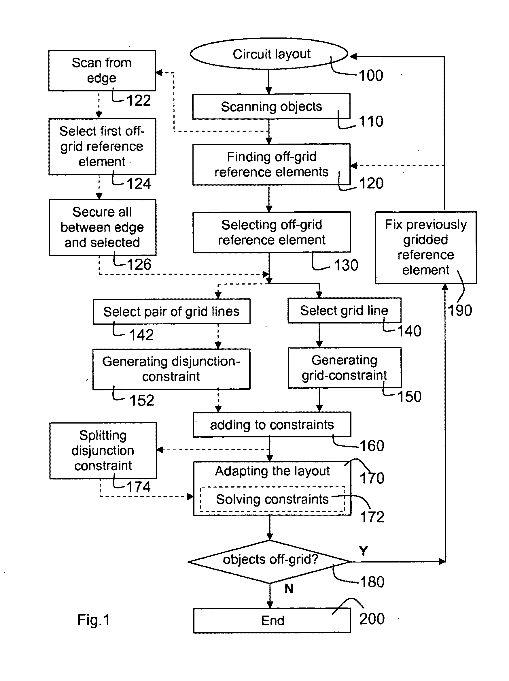
[0024]In an embodiment of the method, the step of selecting a gridline comprises selecting a pair of gridlines arranged on opposite sides of the selected reference element or the selected further reference element, wherein the grid-constraint associated with the selected reference element or the selected further reference element comprises a disjunction-constraint for constraining the selected reference element or the selected further reference element to either one of the gridlines in the selected pair of gridlines. A benefit of this embodiment of the method is that it increases the possibility that the objects can be adapted to substantially comply with the set of constraints, because the selected reference element or the selected further reference element may be moved to either one of the selected pair of gridlines. Typically the circuit layout occupies an area on a
silicon wafer, a so called
footprint. Within this
footprint generally smaller un-used areas may be identified, so call redundant areas. These redundant areas in the circuit layout are used for shifting the objects of the circuit layout to enable the selected reference element or the further selected reference element to be gridded while the compliance of the circuit layout with the design rules is maintained. However, circuit layouts for which, for example, the total
footprint has been minimized (while complying with the design rules), typically have a limited number of redundant areas. Selecting the pair of gridlines on opposite sides of the selected reference element or of the further selected reference element instead of selecting a single gridline enables the use of redundant areas on either side of the selected reference element or the selected further reference element which significantly increases the possibility to find a solution to adapt the objects to substantially comply with the set of constraints.
[0025]In an embodiment of the method, the step of adapting the objects of the circuit layout comprising solving the set of constraints to generate instructions for adapting the circuit layout, wherein the method further comprises a step of: splitting the disjunction-constraint in a first and a second grid-constraint, and solving the set of constraints using the first grid-constraint, the first grid-constraint constraining the selected reference element to a first gridline of the selected pair of gridlines and the second grid-constraint constraining the selected reference element to a second gridline of the selected pair of gridlines, and wherein the second grid-constraint is only used for solving the set of constraints when the set of constraints cannot be solved using the first grid-constraint. A benefit of this embodiment is that the method according to the invention splits the disjunction-constraint into a first and a second grid-constraints, each not being disjunct. The method according to the invention selects the first grid-constraint and tries to solve the set of constraints using the first grid-constraint. If a solution is found using the first grid-constraint, the instructions resulting from the found solution are used to adapt the objects of the circuit layout. If no solution is found using the first grid-constraint, the second grid-constraint is used for solving the set of constraints. By splitting the disjunction-constraint into the first and the second grid-constraints both not being disjunct, the number of solutions for solving the disjunction-constraint is limited and the time required to find a solution to the disjunction-constraint is reduced.
[0027]In an embodiment of the method, the step of selecting the reference element or the further reference element comprises scanning the circuit layout in a scan-direction defined by scanning from an edge of the circuit layout away from the edge along a grid axis and selecting a first reference element or a first further reference element from the edge being unaligned to the predefined grid. The method typically moves the selected reference element or the selected further reference element, and as such also the associated object, within the circuit layout. Generally the design rules are arranged to fit on the predefined grid, for example, a design rule defining a
minimum distance between two objects, or a design rule defining a
pitch between a plurality of objects generally are arranged to fit on the predefined grid on which the circuit layout must be gridded. An example of design rules fitting the predefined grid is, for example, when a distance between
two grid-lines in the predefined grid is equal to a sum of the
minimum distance between two objects and the minimum width of an object. Furthermore, a specific object can only move for gridding when the footprint of the circuit layout contains redundancies which can be used for moving objects of the circuit layout without violating the design rules. If the specific object moves in the direction of the scan direction, intermediate objects of the circuit layout which are located between the specific object and the redundant area will generally move together with the specific object to ensure compliance with the design rules. Due to the fact that the design rules are generally arranged to fit on the predefined grid, many of the intermediate objects will be gridded automatically together with the specific object, resulting in a substantial decrease of the processing time of the method.

