Continuous combined cycle operation power plant and method

Inactive Publication Date: 2010-09-16
GENERAL ELECTRIC CO
View PDF10 Cites 34 Cited by
  • Summary
  • Abstract
  • Description
  • Claims
  • Application Information

AI Technical Summary

Benefits of technology

[0005]A first aspect of the disclosure provides a combined cycle power plant comprising: a gas turbine coupled to a generator; a steam turbine coupled to a generator; a heat recovery steam generator (HRSG) for generating a first steam flow from exhaust from the gas turbine; an auxiliary boiler operatively coupled to the steam turbine for producing a second steam flow having characteristics appropriate for starting the steam turbine; a first control valve for controlling application of the first steam flow to the steam turbine; a second control valve for controlling application of the second steam flow to the steam turbine; and a controller for continuously operating the plant in a combined cycle during operation of the gas turbine by: starting the steam turbine by controlling the second control valve to apply the second steam flow from the auxiliary boiler to the steam turbine, and then

Problems solved by technology

One challenge relative to combined cycle plants is that the steam turbine and the gas turbine have drastically different startup requirements.
The different startup requirements slow overall plant startup, which results in wasted energy and inefficiencies.
Second, the steam required for starting the steam turbine typically requires the gas turbine to be operational, i.e., so that the HRSG generates steam at appropriate conditions.
The steam turbine, however, is a relatively large machine and is more sensitive to changes in temperature during operation.
As a consequence of the limitations posed by the steam turbine startup, the steam generated from the gas turbine's exhaust gas (via the HRSG) cannot all be used immediately, which results

Method used


Image

  • Continuous combined cycle operation power plant and method
  • Continuous combined cycle operation power plant and method
  • Continuous combined cycle operation power plant and method

Examples


Example

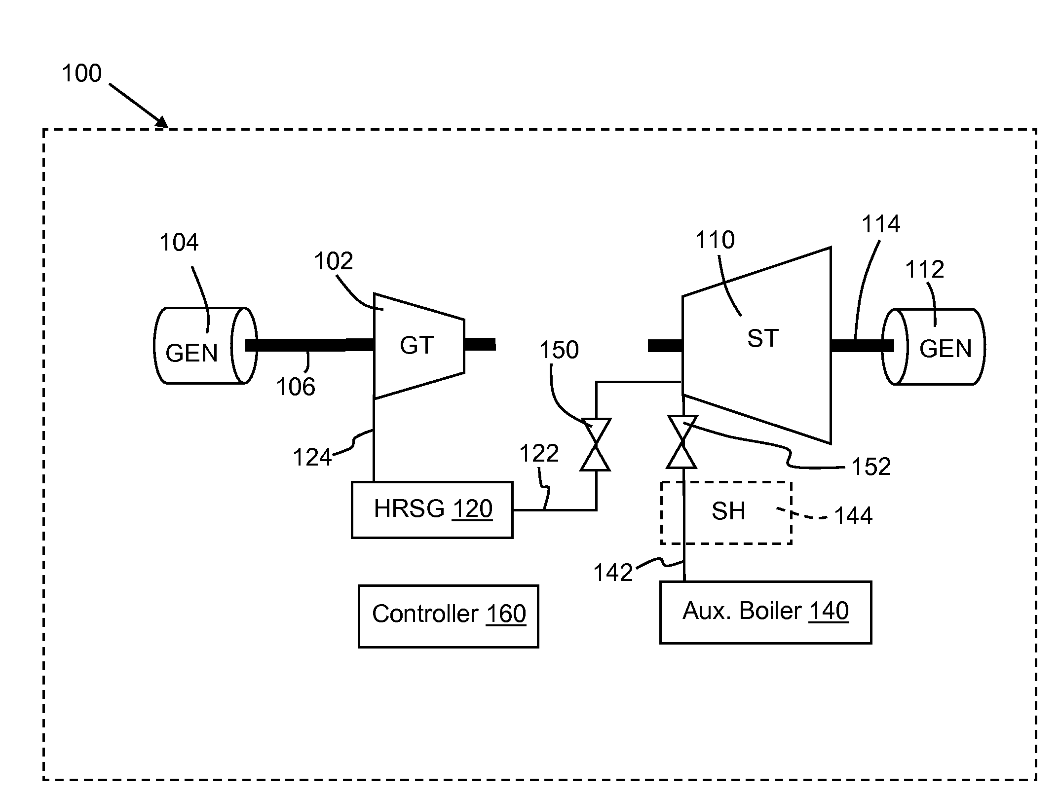
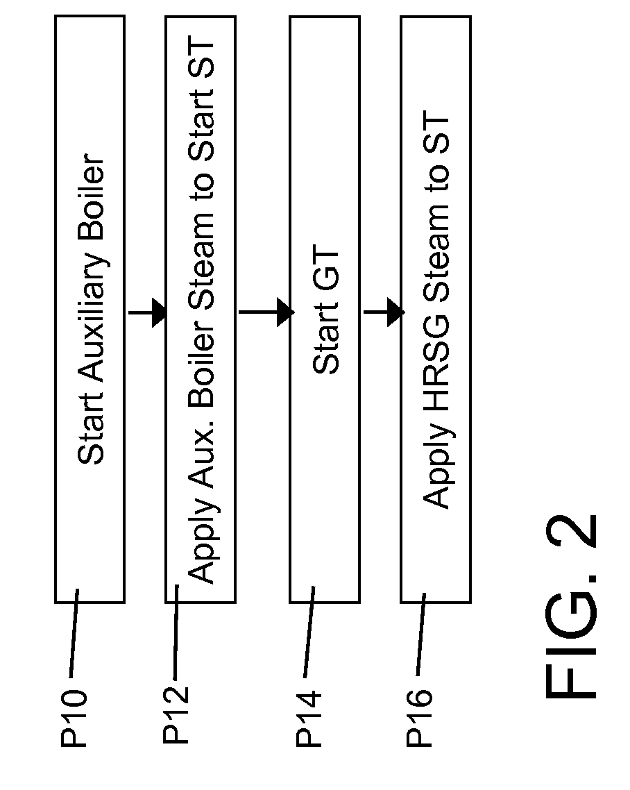
[0010]A combined cycle power plant is described herein that continuously operates in a combined cycle mode during operating of the gas turbine.

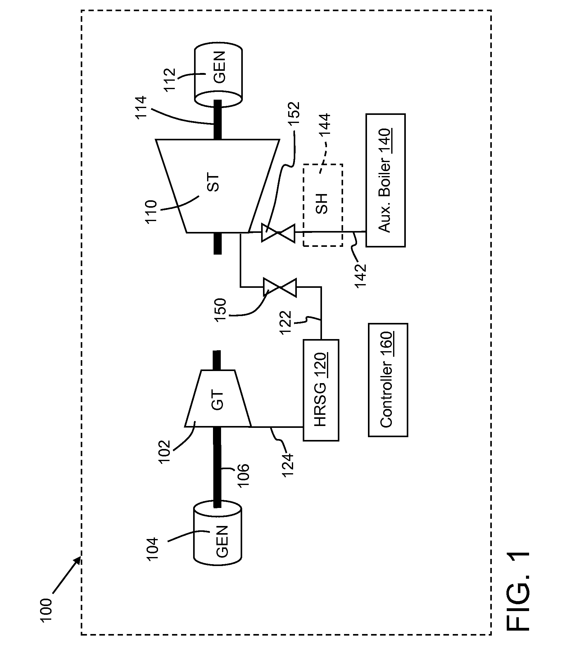
[0011]Referring to FIG. 1, an illustrative combined cycle (CC) power plant 100 according to embodiments of the disclosure is illustrated. (Note the power plant shown in FIG. 1 is simplified for descriptive purposes.) In one embodiment, power plant 100 includes one or more gas turbine(s) (GT) 102 coupled to a generator 104. Gas turbine 102 may include any now known or later developed fuel fired turbine(s), and generator 104 may include any now known or later developed electrical generator(s). A rotating shaft 106 operatively couples gas turbine 102 to generator 104 such that power can be generated from the turning of rotating shaft 106 by gas turbine 102. Power plant 100 also may include a steam turbine (ST) 110 coupled to a generator 112. Steam turbine 110 may include any now known or later developed fuel fired turbine, and generator 112 may ...


PUM


Abstract

A combined cycle power plant includes a gas turbine, a steam turbine, a generator coupled to the gas turbine and a generator coupled to the steam turbine, and an auxiliary boiler operatively coupled to the steam turbine. The power plant is continuously operated in a combined cycle mode during operating of the gas turbine by starting the steam turbine first.

Description

BACKGROUND OF THE INVENTION[0001]The invention relates generally to a combined cycle power plant technology. More particularly, the invention relates to implementing continuous operation for a combined cycle power plant.[0002]A combined cycle power plant uses a gas turbine and a steam turbine to produce energy. To enhance efficiency, the gas turbine's exhaust gas is used in a waste heat recovery steam generator (HRSG) to create steam, which is then applied to the steam turbine.[0003]One challenge relative to combined cycle plants is that the steam turbine and the gas turbine have drastically different startup requirements. The different startup requirements slow overall plant startup, which results in wasted energy and inefficiencies. To illustrate, during startup of the plant, the gas turbine is always started first. This occurs for at least two reasons. First, it is a relatively smaller machine and becomes operational more quickly than the steam turbine; consequently, the HRSG is ...

Claims


Application Information

Patent Timeline
IPC IPC(8): F01K23/08H02K7/18F01K13/02
CPCF01K23/10Y02E20/16F02C6/18
Inventor HOLT, JOEL DONNELLMORAWSKI, CHRISTOPHER JOHNO'CONNOR, MICHAEL JAMES
Owner GENERAL ELECTRIC CO
Why Eureka
Try Eureka