Mooring System for Tidal Stream and Ocean Current Turbines

a technology of mooring system and turbine blade, which is applied in the direction of tidal stream/damless hydropower, sea energy generation, artificial islands, etc., can solve the problems of high drag force of horizontal or vertical axis turbines used to extract energy from the kinetic energy within a moving body of water, the risk of the turbine or the turbine being impacted by the seabed, and the surface floating device experiencing motions induced by surface waves to the detriment of the turbine or

Inactive Publication Date: 2010-09-16
OCEAN FLOW ENERGY
View PDF65 Cites 39 Cited by
  • Summary
  • Abstract
  • Description
  • Claims
  • Application Information

AI Technical Summary

Benefits of technology

[0025]Another advantage of the mooring system of the present invention is that, by placing a substantial element of the overall buoyant upthrust from the system (turbine device plus submerged buoy) into the spread moored buoy, the angle of inclination of the mooring lines with respect to the sea bed may be greater than is the case with mooring systems of the prior art, thus enabling the submerged buoy to be positioned higher in the water column where the current speeds are generally stronger. This is because the greater vertical force imparted into the mooring lines by the submerged buoy ensures that the resultant force vector from the combination of horizontal turbine drag and vertical buoyancy force does not lead to the downstream mooring lines going slack when a tension tethered mooring system is deployed.
[0026]Where the buoyant body is moored such that it occupies a substantially geofixed position the device may rotate about that position and hence align itself with the prevailing current, without requiring a large sea area for the excursions of the device, compared for ins...

Problems solved by technology

Horizontal or vertical axis turbines used to extract energy from the kinetic energy within a moving body of water experience high drag forces as a by-product of the energy extraction process.
This vertical downward acting component of mooring force needs to be balanced by an equal and opposite vertical upward acting force for the device to achieve an equilibrium position in the water column otherwise the device will descend deeper in the water with the risk that the turbine will impact on the seabed.
This has the disadvantage that the surface floating device experiences motions induced by surface waves to the detriment of the performance of the turbine or turbines that are attached to the device.b) Attaching a surface floating buoy to the submerged device to resist the vertical component of the mooring force (for example, the device described in published patent application number UK Patent GB 2256011 B).
This has the disadvantage that the buoy experiences wave induced motions that are transmitted to the turbine device to the detriment of the turbine performance.c) Providing the submerged device with sufficient buoyancy to resist the vertical component of mooring force under the most extreme current drag force to prevent the device grounding on the seabed (for example, the devices described in published patent application numbers WO 03/025385 A2 and WO 03/056169).
This solution has the disadvantage that active means of ballasting will be required to prevent the device exerting too high a buoyant up-thrust when the current drag force is reduced.d) Providing the submerged device with streamline surface piercing buoyant struts that are progressively submerged under the influence of the vertical component of mooring force to provide additional buoyancy force u...

Method used


Image

  • Mooring System for Tidal Stream and Ocean Current Turbines
  • Mooring System for Tidal Stream and Ocean Current Turbines
  • Mooring System for Tidal Stream and Ocean Current Turbines

Examples


Embodiment Construction

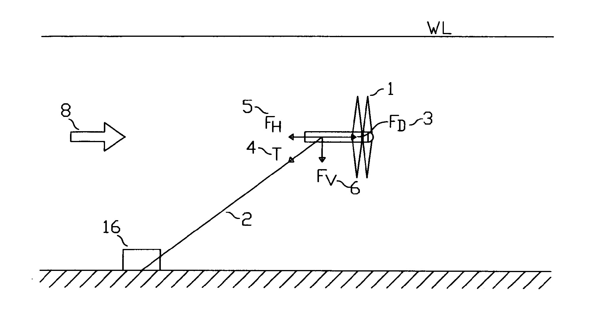
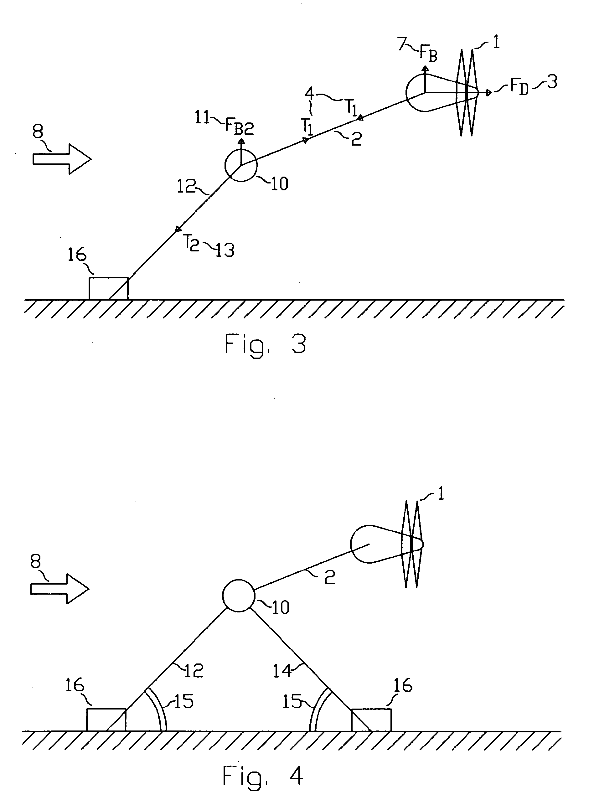
[0042]While various solutions for resisting the vertical downwards acting force induced by a seabed tethered turbine device are described in the Background to the Invention, the invention described hereunder relates to use of a submerged buoyant body to resist the mooring tension induced downwards force. In this arrangement, the buoyancy required to maintain the mooring system in the desired configuration can be provided by the buoyancy in the submerged buoyant body. At a minimum, the turbine need only be neutrally or marginally positively buoyant.

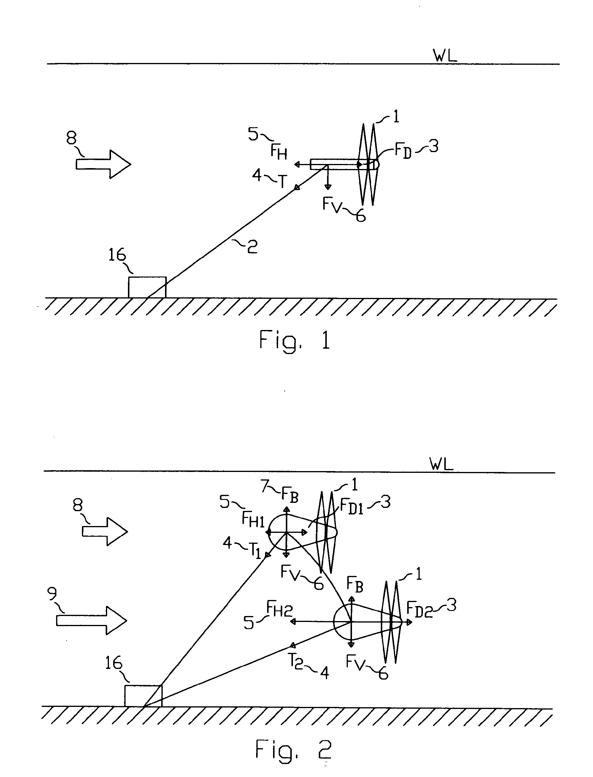
[0043]FIG. 1 illustrates the basic concept of a submerged turbine device with twin counter-rotating turbines (1) tethered by a mooring line (2) which is fixed at one end to the seabed by an anchor (16). The forces acting on the mooring line used to constrain a horizontal axis turbine device placed in a flow of water in a mooring system of the prior art are illustrated. The turbine device which is assumed to be neutrally buoyant experiences...


PUM


Abstract

A tidal stream or ocean current turbine is connected to a submerged buoy that is tethered to the seabed to create a virtual seabed level that is higher than the actual seabed. The buoy is constrained by tensioned tethers or catenary mooring lines such that it is approximately geofixed at a prescribed depth of immersion and orientation. The turbine device is attached to the submerged buoy by a connector strut that allows the device to swivel about the geofixed location. The strut to buoy connection incorporates a bearing system that allows the strut freedom of rotation in the horizontal and vertical planes about the geofixed buoy. The reserve of buoyancy in the submerged buoy acts to resist the vertical component of the mooring force such that the drag force on the turbine device cannot lead the device to submerge excessively or cause the downstream tension tether mooring lines to go slack.

Description

FIELD OF THE INVENTION[0001]The present invention relates to the extraction of energy from tidal streams and ocean currents by means of a turbine, and in particular to a mooring system for such a turbine.BACKGROUND OF THE INVENTION[0002]Tidal streams and ocean current can be used to generate power by placing a horizontal or vertical axis turbine in the flow. For deep water tidal stream and ocean current sites the turbine can be supported by buoyancy and tethered to the seabed by a mooring system.[0003]Horizontal or vertical axis turbines used to extract energy from the kinetic energy within a moving body of water experience high drag forces as a by-product of the energy extraction process. If a device fitted with a turbine (1) is moored off to the seabed the mooring line (2), which is subject to a large horizontal drag force FD generated by the turbine, must apply a tension force T to the device which can be resolved into a horizontal force FH which is equal and opposite to FD and a...

Claims


Application Information

Patent Timeline
IPC IPC(8): F03B13/10
CPCE02B2017/0091Y02E10/38Y02E10/28F03B17/061Y02E10/30F03B13/264Y02E10/20
Inventor MACKIE, GRAEME CHARLES
Owner OCEAN FLOW ENERGY
Why Eureka
Try Eureka