Microbubble optical resonator

a micro-bubble optical resonator and optical sphere technology, applied in semiconductor lasers, instruments, other domestic objects, etc., can solve the problems of difficult “tune” and adjustment, difficult to maintain and control optical microspheres on a repeated basis, and difficult to use optical microspheres as filtering elements, etc., to improve rigidity and stability of the device, and high coupling efficiency

Active Publication Date: 2010-09-16
OFS FITEL LLC
View PDF35 Cites 18 Cited by
  • Summary
  • Abstract
  • Description
  • Claims
  • Application Information

AI Technical Summary

Benefits of technology

[0013]In accordance with the present invention, a micro “bubble” is formed along an optical microcapillary. The “bubble” comprises a curved film of optically transparent material that can be created while the microcapillary is still in its malleable form. The curvature creates an optical resonator with a geometry that encourages the circulating WGMs to remain confined in the central region of the bubble, preventing the wandering associated with the microcapillary-based prior art LCORRS devices. By confining the propagating signal in this fashion, fewer modes will be supported and provide the wavelength separation required for filtering applications. The geometry of the bubble itself is not necessarily spherical, but may exhibit an elongated or ‘squeezed’ bubble profile. Indeed, one or more separate bubbles, or one or more “curves” on the outer surface of the microcapillary have been found sufficient to confine the circulating WGMs in a manner which forms a high Q resonator.
[0014]The microbubble optical resonator of the present invention may be used as a filter, sensor or laser, with a material to be sensed (liquid, gas, solid) or active laser material (liquid, gas or solid) injected along the microcapillary within which the microbubble is formed. An optical signal is coupled into the microbubble via an associated optical waveguide, prism, grating, tapered fiber or other suitable coupling device. A coupling tapered fiber may take the form of an optical microfiber including a tapered region formed to contact the surface of the microbubble and provide high coupling efficiency between the fiber and the microbubble. The thickness of the curved film of the microbubble's outer surface is also a factor in determining the coupling efficiency between the optical coupling path (waveguide, prism, fiber) and the microbubble resonator.
[0015]The use of a microbubble formed along a section of optical microcapillary allows for the sensor to retain the preferable qualities of the prior art LCORRS devices in terms of robustness and ease of use. That is, the sample being tested (or the amplifying medium) will still pass along the microcapillary / bubble structure and remain physically isolated from the optical fiber (or prism, grating, waveguide, etc.) supporting the propagating optical signal used in various applications.
[0016]The microbubble resonator of the present invention may be disposed within and encapsulated by a polymer matrix material having a relatively low index of refraction. The encapsulation functions to improve the rigidity and stability of the device. In this embodiment, an etchant may be used to remove the microcapillary material in the region of the microbubble, forming a cavity within the encapsulant that functions as the microbubble resonator.

Problems solved by technology

In some conventional arrangements, the material is contained with an optical microfiber probe which must be positioned at the surface of the microsphere, which is both awkward and difficult to maintain and control on a repeated basis.
Additionally, optical microspheres are difficult to use as a filtering element, since they are relatively rigid in structure and difficult to “tune” to adjust the wavelength(s) passed / blocked by the microsphere device.
Another problem, which is characteristic for the microsphere optical cavity, is the very dense and practically chaotic distribution of its resonant frequencies, making the microsphere difficult to use in filtering applications.
However, problems remain with the sensitivity that may be achieved with an LCORRS device.
Thus, the localized eigenmodes of the circulating WGMs do not remain confined to waist region W and, therefore, the Q-factor of the device is rather limited.
Thus, a tension remains between these two types of prior art sensors, where the microsphere / microtoroid has the advantage of desirable high Q-factor, but is not robust or practical in implementation, while the LCORRS sensor is very robust and applicable in many situations, but has limits on the Q-factor that may be achieved.

Method used


Image

  • Microbubble optical resonator
  • Microbubble optical resonator
  • Microbubble optical resonator

Examples


Embodiment Construction

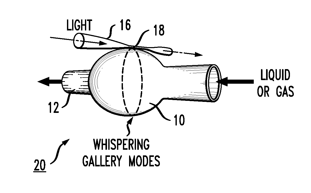
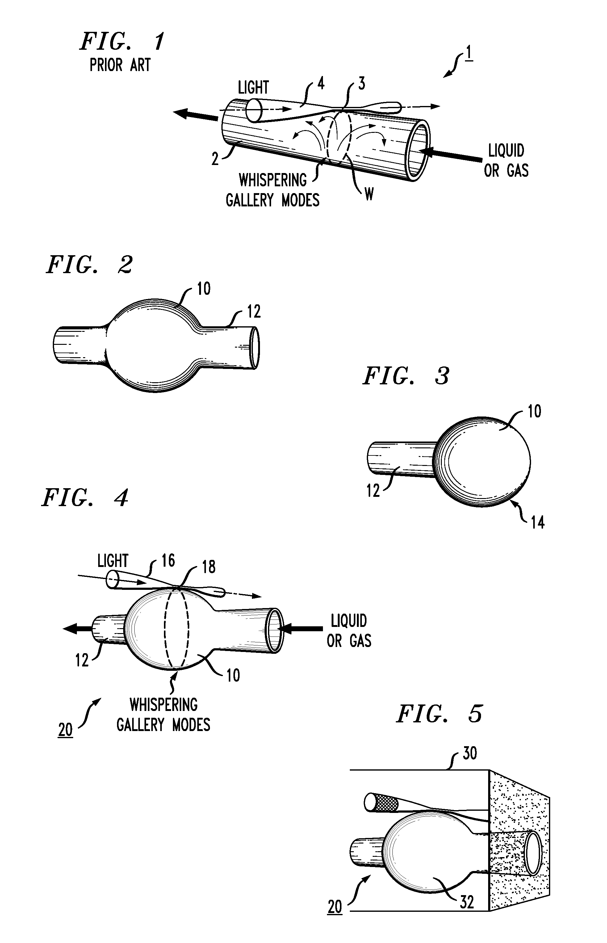
[0028]FIG. 2 illustrates an exemplary microbubble 10 formed along a section of optical microcapillary 12 in accordance with the principles of the present invention. As shown, the “bubble” takes the form of a curved film of optically transparent material, in this case the material used to form microcapillary 12 itself. Various methods may be used to create microbubble 10, where an exemplary method utilizes local melting of a section of microcapillary 12 while under pressure. FIG. 3 illustrates an alternative arrangement, with a microbubble 10 formed at a terminal portion 14 of microcapillary 12. In either configuration, it is to be understood that the microbubble need not be ‘spherical’ in form, and may take the shape of an elongated or squeezed bubble. One or more such microbubbles may be formed along a section of microcapillary and the bubble(s) may dominate the entire extent of the microcapillary, or only a portion thereof.

[0029]Optical microbubble resonator 10 as shown in FIG. 2 ...


PUM

PropertyMeasurementUnit
diametersaaaaaaaaaa
thicknessaaaaaaaaaa
optically transparentaaaaaaaaaa

Abstract

An optical microresonator is configured as an optical microbubble formed along a section of an optical microcapillary. The curvature of the outer surface of the microbubble creates an optical resonator with a geometry that encourages the circulating WGMs to remain confined in the central region of the bubble, creating a high Q optical resonator. The resonator may be tuned by modifying the physical properties of the microbubble, allowing the resonator to be used as an optical filter. The resonator may also be used as a sensor or laser by introducing the material to be sensed (or the active laser material) into the microcapillary along which the microbubble is formed.

Description

CROSS-REFERENCE TO RELATED APPLICATIONS [0001]This application claims the benefit of U.S. Provisional Application No. 61 / 159,822, filed Mar. 13, 2009 and herein incorporated by reference.TECHNICAL FIELD [0002]The present invention relates to an optical microresonator and, more particularly, to a microbubble-type optical resonator formed along a section of an optical microcapillary.BACKGROUND OF THE INVENTION[0003]Microcavity optical resonators are a basic element of many photonic circuits, including filters, sensors, lasers and the like. Ever-increasing demands for improvement in the operation of microcavity resonators are associated with parameters such as their Q-factor, tunability (filtering), robustness and efficiency. Particularly important realizations of the optical microcavity are the “microsphere” and “microtoroid”. An optical microsphere is used to form an optical whispering-gallery-mode (WGM) resonator that supports a special set of resonator modes. These resonator modes ...

Claims


Application Information

Patent Timeline
Patent Type & Authority Applications(United States)
IPC IPC(8): G01N1/20H01S3/08B29D22/00
CPCG01N21/05G01N21/7746G01N2021/0378G02B6/29341G02B6/29335H01S5/10H01S5/1075G01N2021/0346G02B5/20H01S3/083
Inventor SUMETSKY, MIKHAIL
Owner OFS FITEL LLC
Why Eureka
Try Eureka