
Method and device for measuring emissions of gaseous substances to the atmosphere using scattered sunligt spectroscopy
a gaseous substance and emission measurement technology, applied in the field of gaseous substance emission measurement to the atmosphere using scattered sunligt spectroscopy, can solve the problems of only measuring emission, power consumption of the device, and not being able to determine unambiguously the clean air background
- Summary
- Abstract
- Description
- Claims
- Application Information
AI Technical Summary
Benefits of technology
Problems solved by technology
Method used
Image

Examples
Embodiment Construction
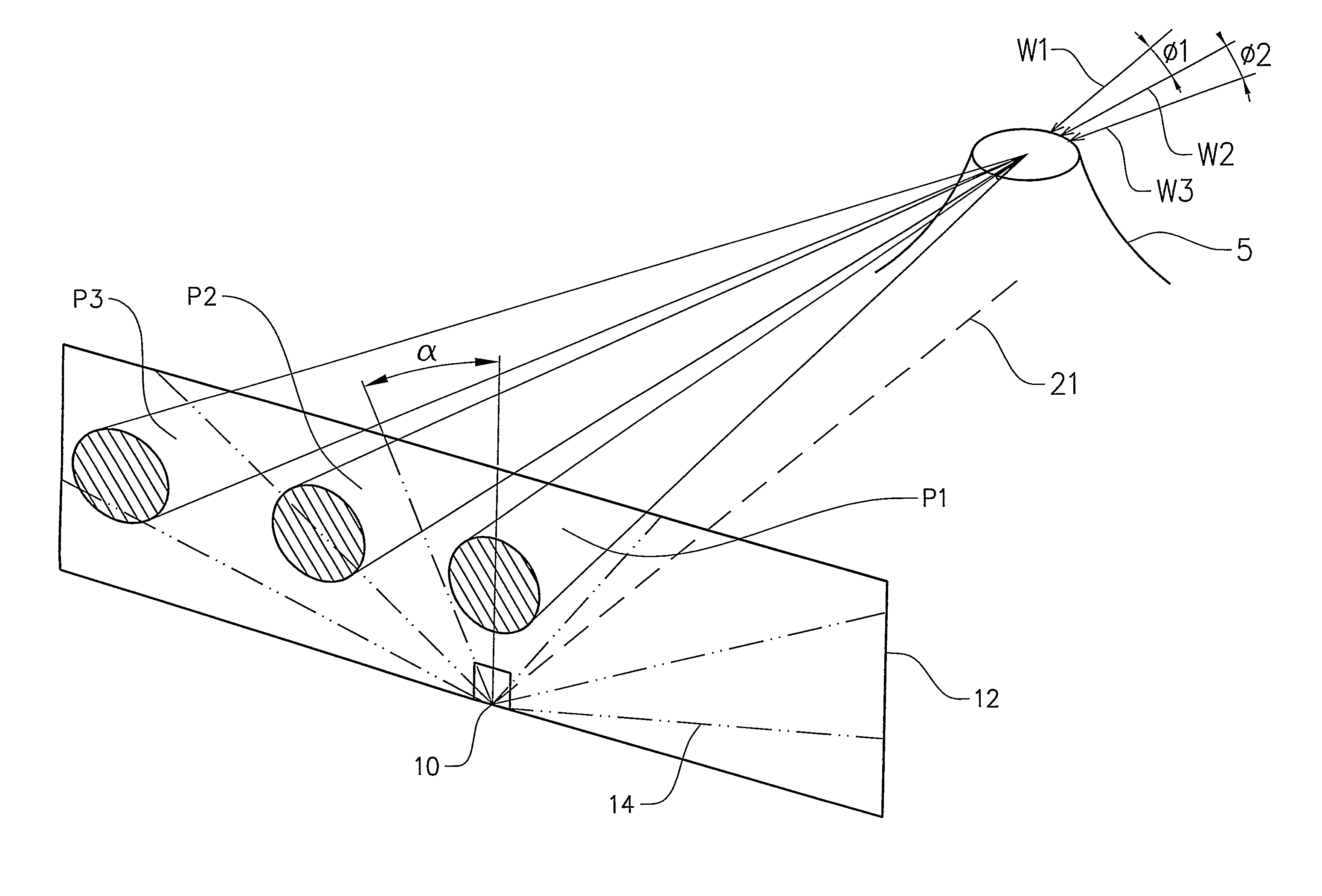
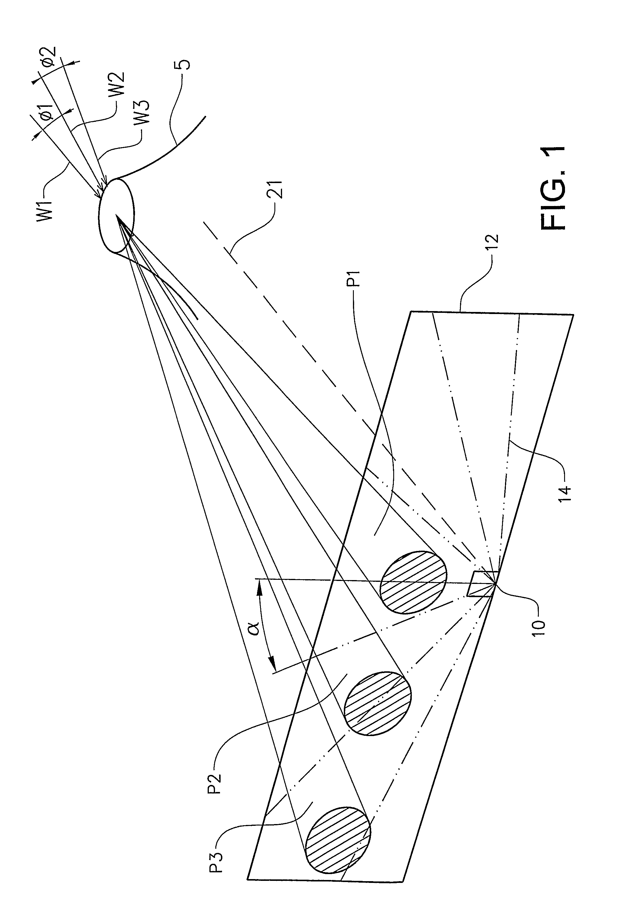
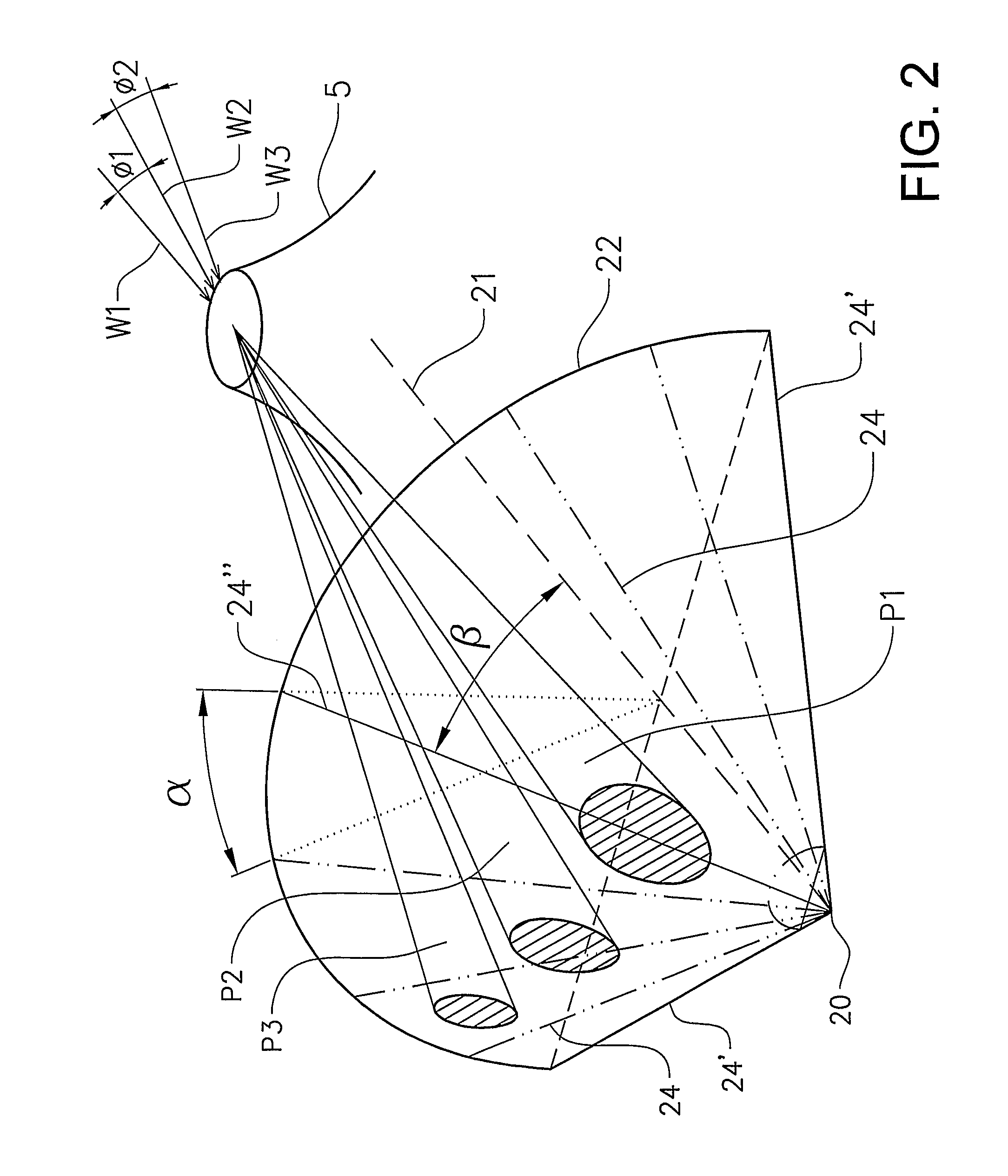
[0037]FIGS. 1 and 2 show a 3-d representation of the measurement strategies for the prior art and the present invention, respectively. FIG. 1 gives a principal illustration of the use of a prior art optical measuring device 10 in the form of a scanning mini-DOAS in measurements of a gas emission from a source in the form of a volcano 5. In particular, FIG. 1 illustrates the effect of different plume directions relative to the location of the measuring device 10. Three different plumes P1, P2 and P3 represent three different wind directions W1, W2 and W3. The first wind direction W1 is directed from the gas emission source 5 towards the measuring device 10 resulting in that the corresponding plume P1 passes right above the measuring device 10. The second wind direction W2, and thus the direction of the second plume P2, exhibit an angle Φ1 relative to the direction of W1 and P1 such that the second plume P2 passes above the measuring device 10 somewhat at the side. The third wind dire...
PUM
 Abstract
Description
Claims
Application Information