Condensing film for LCD backlight unit and LCD backlight unit using the same

Inactive Publication Date: 2010-09-16
LG CHEM LTD
7 Cites 8 Cited by

AI-Extracted Technical Summary

Problems solved by technology

However, the increase in the number of the stacked optical films makes it possible to improve the image quality, but th...

Method used

[0029]The condensing film according to the present invention has a prominence-depression pattern whose prominences are formed at constant distances, and the light ingoing unit 20 having a reflection plane 50 formed therein is provided in each of the prominences, as shown in FIG. 3. This is done to facilitate the formation of the reflection planes. When the prominence-depression pattern is formed in the light ingoing unit 20, the reflection planes 50 may be easily formed by coating the prominences with materials, such as reflectance UV ink, reflective heat-transfer film, that give reflective characteristics to a surface of the light ingoing unit 20, etc. (hereinafter, referred to as a “reflection plane material”) using a suitable tool such as a roller.
[0030]The reflection planes 50 formed thus functions to improve the use efficiency and optical characteristics of the light by cutting off light that moves along a path on which the light does not focus, and reflecting the light in a direction toward a light source. The reflection plane material preferably contains 50% or more by weight of titanium dioxide.
[0032]The use of the curable resin makes it possible to easily manufacture the light ingoing unit 20 by using a method such as molding, and form the prominence-depression pattern with desired shape, size and pitch in the light ingoing unit 20. Also, a condensing film including the light diffuser 70 may be easily manufactured using a method including: dispersing a curable resin with a light diffuser 70, molding a mixture of the curable resin and the light diffuser and curing the mixture.
[0033]Meanwhile, the light outgoing unit 30 is formed in an upper surface of the film unit 10, and generally composed of lenticular lenses. As described above, the lenticular lens functions to improve brightness (luminance) of light within a visible range by focusing the light passed through...

Benefits of technology

[0017]The LCD backlight unit according to the present invention may be useful to widen a viewing angle and prevent the formation of hot bands by improving luminance distribution characteristics of light emitted from the condensing film since a light diffuser for diffusing the light is included inside the condensing film.
[0018]Also, the LCD backlight unit according to the present invention may be useful to easily form reflection planes with a reflectance UV ink by forming a prominence-depression pattern in the light ingoing unit.
[0019]In addition, the LCD b...

Abstract

There is provided a condensing film for an LCD backlight unit. The condensing film including a film unit; a light outgoing unit formed in an upper surface of the film unit; and a light ingoing unit formed in a lower surface of the film unit, wherein a light diffuser is included inside the condensing film. The condensing film may be useful to widen a viewing angle and prevent the formation of hot bands by improving luminance distribution characteristics of light emitted from the condensing film since the condensing film includes a light diffuser capable of diffusing the light.

Application Domain

Diffusing elementsCondensers +3

Technology Topic

Hot bandEngineering +2

Image

  • Condensing film for LCD backlight unit and LCD backlight unit using the same
  • Condensing film for LCD backlight unit and LCD backlight unit using the same
  • Condensing film for LCD backlight unit and LCD backlight unit using the same

Examples

  • Experimental program(3)

Example

Example 1
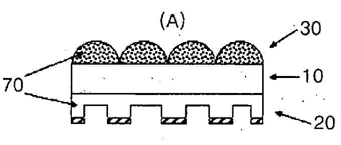
[0043]20 g of a bead-type PMMA polymer (refractive index: 1.49, mean particle diameter: 15 μm (micrometer)) was dispersed in 100 g of a UV-curable resin having a refractive index of about 1.53 to prepare a curable resin solution. A lenticular lens and a light ingoing unit were formed respectively in upper and lower surfaces of a PET film by pouring the curable resin solution between a roller-type mold and a 125 μm (micrometer)-thick PET film and curing the curable resin solution. Then, reflection planes were formed in prominences of the light ingoing unit by coating the prominences with a reflectance ink.

Example

Comparative Example 1
[0044]The condensing film was manufactured in the same manner as in the Example 1, except that the bead-type PMMA polymer was not added to the curable resin solution.

Example

Experimental Example 1
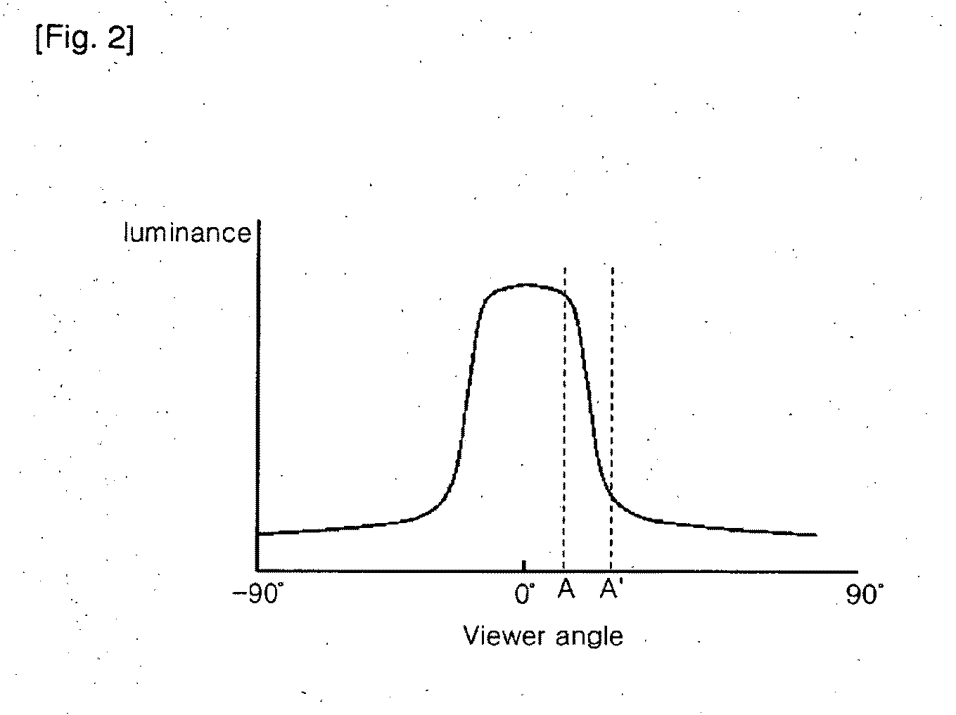
[0045]Each of the condensing film prepared in the Example 1 and Comparative example 1 was stacked onto an edge-type light guide plate using a BM7 (commercially available from Nikon) provided in a Goniometer, and measured for luminance distribution according to the viewing angle in a vertical direction. The experimental results were plotted in the graph as shown in FIG. 5.
[0046]As shown in FIG. 5, it was revealed that the condensing film of Comparative example 1 shows a sudden reduction in the luminance around a viewing angle of about ±20° (degree) but the condensing film of Example 1 shows a gentle change in the luminance around the viewing angle. Since hot bands appeared by the sudden changed in the luminance as described above, the formation of the hot bands may be reduced by using a condensing film, such as the condensing film of Example 1, that shows the gentle change in the luminance, which makes it possible to display an image with excellent image quality.
INDUSTRIAL APPLICABILITY
[0047]As described above, an aspect of the present invention provides a backlight unit for an LCD including the above-mentioned condensing film. The backlight unit according to the present invention may be useful to improve the image quality without any diffusion film and reduce the production cost since the light diffuser in the condensing film functions to prevent a hot band phenomenon by softening the luminance distribution of the light.

PUM

no PUM

Description & Claims & Application Information

We can also present the details of the Description, Claims and Application information to help users get a comprehensive understanding of the technical details of the patent, such as background art, summary of invention, brief description of drawings, description of embodiments, and other original content. On the other hand, users can also determine the specific scope of protection of the technology through the list of claims; as well as understand the changes in the life cycle of the technology with the presentation of the patent timeline. Login to view more.

Similar technology patents

Integrated circuit device

InactiveUS20050218470A1easily formprevent any influence
Owner:RENESAS ELECTRONICS CORP

Flare-shaped end structure for tube

ActiveUS20070052236A1easily formhigh rigidity
Owner:SANOH KOGYO KK

Classification and recommendation of technical efficacy words

Why Eureka
Try Eureka