Method and apparatus for manufacturing resin stamper, imprint method, magnetic recording medium, and magnetic recording/reproducing apparatus

a technology of resin stamping and imprinting, which is applied in the direction of manufacturing tools, instruments, dough shaping, etc., can solve the problems of difficult to increase the surface recording density, bit error rate, and decrease the snr, so as to achieve low cost and low cost. , the effect of low cos

Inactive Publication Date: 2010-09-23
SHOWA DENKO KK
View PDF12 Cites 12 Cited by
  • Summary
  • Abstract
  • Description
  • Claims
  • Application Information

AI Technical Summary

Benefits of technology

[0080]According to the present invention, it is possible to transfer the pattern of the mother stamper to the resin composite base material, and thus manufacture a resin stamper with a pattern at a low cost. The resin stamper is used to form a pattern on a thin film of, for example, a magnetic recording medium by an imprint method, and the pattern formed on the thin film is used to remove a pattern from a portion of the magnetic film or make a portion of the magnetic film non-magnetic according to the pattern. In this way, it is possible to form a pattern on the magnetic film. The use of the resin stamper makes it possible to implement an imprint method at a lower cost than a precise metal stamper used in the imprint method according to the related art, such as a Ni alloy stamper manufactured by electroforming. Therefore, it is possible to form a pattern on the magnetic film of the magnetic recording medium at a low cost.
[0081]The resin stamper is cheaper than that of a precise metal stamper, such as a Ni alloy stamper manufactured by electroforming. Therefore, when the resin stamper is used to form a pattern on a thin film of a magnetic recording medium, it is possible to easily replace the resin stamper at a low cost even when the resin stamper is replaced more frequently than the Ni alloy stamper due to dust adhesion. Therefore, even when the resin stamper is replaced more frequently than the Ni alloy stamper, the manufacturing costs are less likely to increase. For example, when magnetic recording media are manufactured while frequently replacing the resin stampers, it is possible to reduce the number of defective products manufactured, even when defects occur due to dust adhesion during manufacture, as compared to the case in which a metal stamper, such as a Ni alloy stamper, is used to manufacture a large number of magnetic recording media.
[0082]According to the present invention, both a pattern transfer process and a process of punching the base material using the cutter member are performed. Therefore, it is possible to easily obtain a resin stamper having a desired shape and a desired pattern transferred thereto. In the pattern transfer process, the mother stamper is pressed against a resin composite base material to transfer the pattern of the mother stamper to the resin composite base material by compression molding, and the curing resin is cured by active energy beams or heat, thereby transferring a pattern. As a result, it is possible to accurately transfer a fine pattern, and thus obtain a resin stamper having a desired fine pattern formed thereon.
[0083]In the present invention, a film or sheet that transmits 20% or more of ultraviolet rays in the wavelength range of 200 nm to 400 nm is used, and a curing resin layer having a curing functional group is formed thereon. Therefore, it is possible to sufficiently radiate active energy beams to the curing resin without hindering the active energy beams from reaching the curing resin. As a result, it is possible to reliably cure the curing resin layer, and thus reliably transfer a fine pattern.
[0084]According to the apparatus for manufacturing a resin stamper of the present invention, it is possible to transfer the pattern of a mother stamper to a resin composite base material, and punch the resin base material or composite base material into a desired shape. As a result, it is possible to manufacture a resin stamper having a desired shape and a desired pattern.
[0085]In the manufacturing apparatus according to the present invention, the cutter member includes an inner circumferential cutter blade or an outer circumferential cutter blade. According to this structure, it is possible to punch the inside or outside of the pattern of the base material to manufacture a resin stamper having a desired shape.

Problems solved by technology

However, when the track density increases, magnetic recording information items in adjacent tracks interfere with each other, and a magnetization transition area at the boundary therebetween serves as a noise source, which may decrease the SNR.
The lowering of the SNR causes a reduction in bit error rate (bit error rate), which makes it difficult to increase the surface recording density.
However, when the size of the recording bit is greatly reduced, a minimum magnetization volume per bit is reduced, which may cause recorded data to be erased due to magnetization reversal caused by heat fluctuation.
The method can minimize the influence between adjacent tracks, but it is difficult to obtain a sufficient reproduction output, which makes it difficult to ensure a sufficiently high SNR.
However, since the uneven pattern formed on the substrate is transferred to the formed film, the floating posture and the floating height of a recording / reproducing head that records or reproduces data while floating from the medium become unstable.
In order to meet the demands, with the development of a lithography technique, which is the core technology of a semiconductor device process, the cost of an apparatus has increased.
However, with the development of fine pattern lithography, the cost of the exposure apparatus has exponentially increased, and the cost of a mask for obtaining the same resolution as the light wavelength used has suddenly increased.

Method used


Image

  • Method and apparatus for manufacturing resin stamper, imprint method, magnetic recording medium, and magnetic recording/reproducing apparatus
  • Method and apparatus for manufacturing resin stamper, imprint method, magnetic recording medium, and magnetic recording/reproducing apparatus
  • Method and apparatus for manufacturing resin stamper, imprint method, magnetic recording medium, and magnetic recording/reproducing apparatus

Examples


first embodiment

[0135]Hereinafter, exemplary embodiments of the present invention will be described with reference to the accompanying drawings, but the present invention is not limited to the following embodiments.

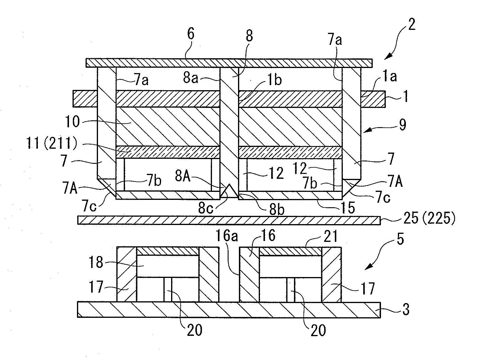
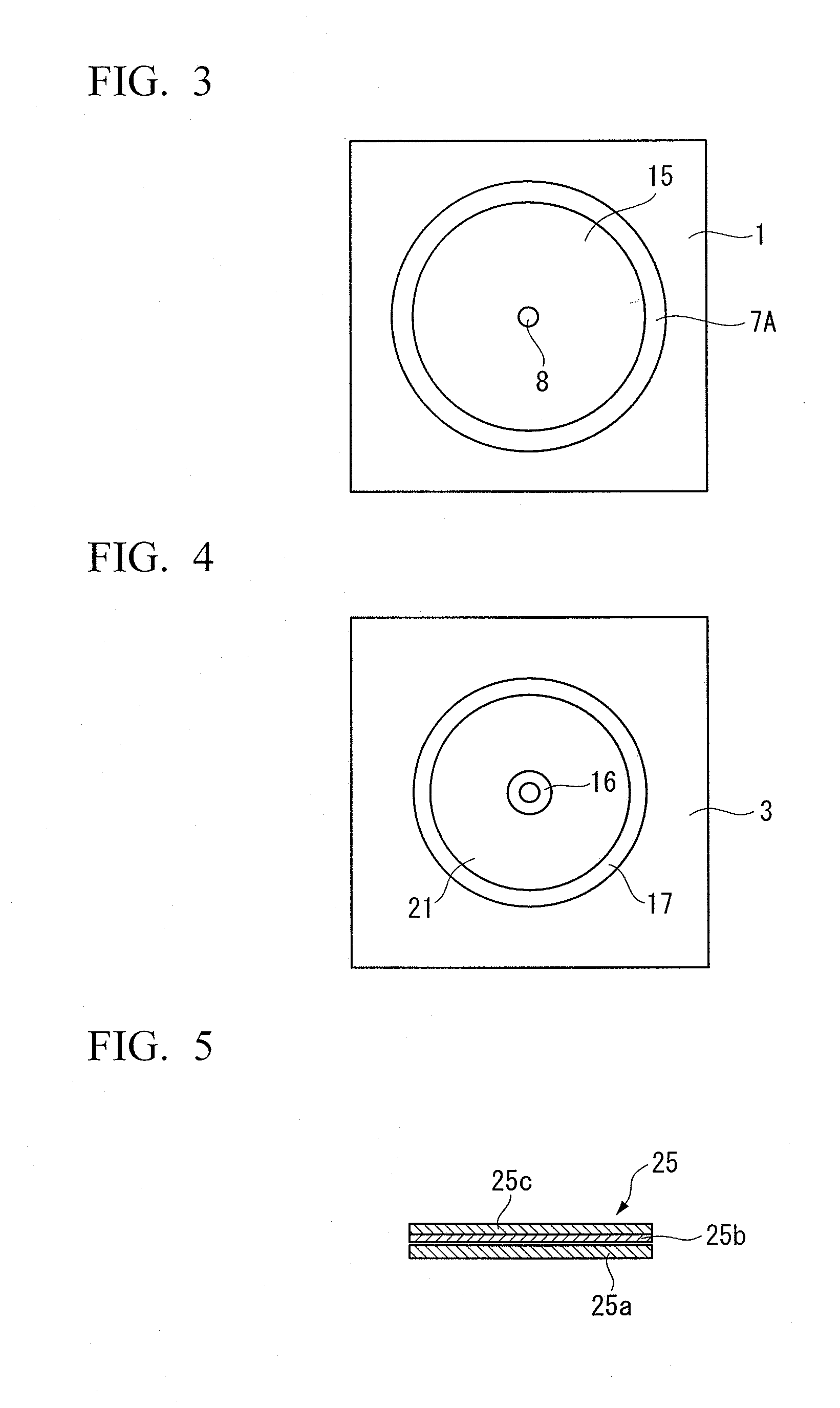
[0136]FIGS. 1 to 9 are diagrams illustrating an apparatus for manufacturing a resin stamper according to a first embodiment of the present invention. As shown in FIG. 1, the manufacturing apparatus includes an upper set 2 supported by a first mounting plate 1 and a lower set 5 supported by a second mounting plate 3. The first mounting plate 1 is supported by an actuator for movement in the vertical direction, such as a hydraulic cylinder (not shown) so as to be movable in the vertical direction, and the second mounting plate 3 is fixed to a base (not shown).

[0137]In this embodiment, the structure of an apparatus for manufacturing a doughnut disk-shaped resin stamper will be described below. The shape of the resin stamper is not limited to the doughnut disk shape, but the resin stamper ma...

second embodiment

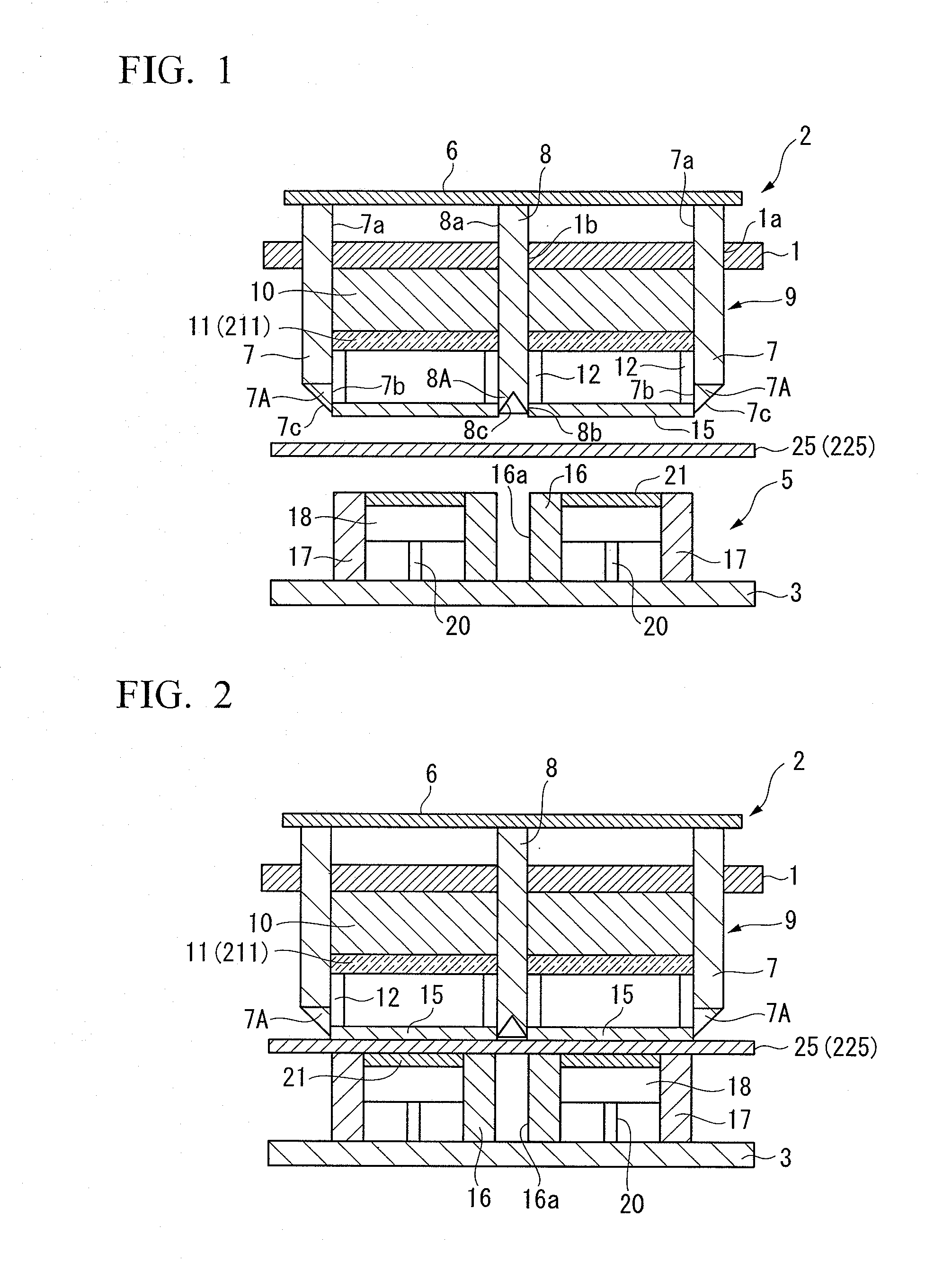
[0313]Next, a second embodiment of the present invention will be described in detail with reference to the accompanying drawings. The structure of a resin stamper manufacturing apparatus according to this embodiment is similar to that of the resin stamper manufacturing apparatus according to the first embodiment, except that a heating device 211 is provided instead of the radiating device 11 in the resin stamper manufacturing apparatus according to the first embodiment, so that heat generated by a heat source, such as a heater provided in the heating device 211, can be transmitted downward. Therefore, in the resin stamper manufacturing apparatus according to this embodiment, a description of the same components as those in the first embodiment will be omitted.

[0314]In order to manufacture a resin stamper using the manufacturing apparatus having the structure shown in FIG. 1, a base material of the resin stamper is prepared.

[0315]As an example of the base material, any of the followi...

examples

[0351]A one-component silicone rubber adhesive PURE-SEALANT CLEAR TYPE (manufactured by Shin-Etsu Chemical Co., Ltd., the elastic modulus after curing: 0.76 MPa) was applied with a thickness of 20 μm on a polycarbonate sheet having a thickness of 0.3 mm (PANLITE SHEET PC2151 manufactured by Teijin Chemicals, Ltd, glass transition temperature: 160° C. and tensile modulus: 2.4 GPa), and a cycloolefin polymer sheet with a thickness of 0.1 mm (ZEONOR 1060R manufactured by Zeon Corporation, glass transition temperature: 100° C. and tensile modulus: 2.1 GPa) was formed on the adhesive so as to be planarized. Then, the laminate was maintained at a temperature of 25° C. and 50% RH for one hour.

[0352]The mother stamper was set in the apparatus shown in FIG. 1 with its pattern surface facing upward, and the mold was warmed at a temperature of 70° C. The cutter blades 7 and 8 of the apparatus shown in FIG. 1 were made of stainless steel, and the translucent pressing base 15 was made of tempere...


PUM

PropertyMeasurementUnit
wavelength rangeaaaaaaaaaa
thicknessaaaaaaaaaa
glass transition temperatureaaaaaaaaaa

Abstract

The present invention provides a technique capable of manufacturing a resin stamper at a low cost. A method of manufacturing a plate-shaped resin stamper includes: pressing a resin composite base material against a mother stamper having a pattern formed on the surface thereof by compression molding to transfer the pattern of the mother stamper to the composite base material; and punching the composite base material. In the manufacturing method, the resin composite base material includes at least one curing resin. In addition, during the compression molding, a portion of the composite base material is cured by active energy beams or heat, the pattern is transferred to the composite base material, and the composite base material is punched, thereby manufacturing the resin stamper.

Description

TECHNICAL FIELD[0001]The present invention relates to a method and apparatus for manufacturing a resin stamper that has a pattern transferred thereto and a positioning hole formed at the center or the edge thereof, a magnetic recording medium manufactured by the method and apparatus, and a magnetic recording / reproducing apparatus including the magnetic recording medium.[0002]Priority is claimed on Japanese Patent Application No. 2007-273006, filed Oct. 19, 2007, Japanese Patent Application No. 2007-299900, filed Nov. 19, 2007, and Japanese Patent Application No. 2008-009396, filed Jan. 18, 2008, and the contents of which are incorporated herein by reference.BACKGROUND ART[0003]In recent years, the application range of magnetic recording devices, such as magnetic disk devices, flexible disk devices, and magnetic tape devices, has been significantly widened, and the importance thereof has increased. In addition, a technique for improving the surface recording density of magnetic recor...

Claims


Application Information

Patent Timeline
Patent Type & Authority Applications(United States)
IPC IPC(8): G11B3/72B29C33/42B29C35/08B28B11/08
CPCB29B13/023B29C35/0805B29C43/021G11B5/855B29C2043/025B29L2017/003B29C43/40
Inventor UCHIDA, HIROSHIFUKUSHIMA, MASATOSAKATA, YUKO
Owner SHOWA DENKO KK
Why Eureka
Try Eureka