
Apparatus for detecting brain conditions

a technology for detecting brain conditions and apparatuses, applied in applications, instruments, catheters, etc., can solve the problem of most of the near infrared light remaining, and achieve the effects of improving accuracy and reliability, minimizing damage to brain tissue, and small size and weigh

Inactive Publication Date: 2010-09-23
KOREA INST OF SCI & TECH
View PDF4 Cites 19 Cited by
  • Summary
  • Abstract
  • Description
  • Claims
  • Application Information

AI Technical Summary

Benefits of technology

[0007]The embodiments of this disclosure may provide an apparatus capable of detecting brain conditions such as blood flow rate, oxygen saturation, etc. with improved accuracy and reliability as embedded at a location adjacent to the brain of humans or animals.
[0009]The apparatus for detecting brain conditions according to the embodiments of the disclosure is capable of detecting brain conditions at a location relatively adjacent to the brain, and thus may improve accuracy and reliability of detection. The apparatus for detecting brain conditions may be used to detect brain conditions such as blood flow rate, oxygen saturation, etc., and thus may immediately cope with emergency situations. Further, it may be employed in various applications including neurosurgery, surgery, internal medicine, emergency medicine, or the like since monitoring of brain activities is possible. In addition, since it has a relatively small size and weight in addition to its flexibility, it may minimize damage to the brain tissue.

Problems solved by technology

However, when such an apparatus is used, most of the near infrared light remains in the scalp or the skull, not passing through the brain.

Method used


Image

  • Apparatus for detecting brain conditions
  • Apparatus for detecting brain conditions
  • Apparatus for detecting brain conditions

Examples


Embodiment Construction

[0017]Exemplary embodiments now will be described more fully hereinafter with reference to the accompanying drawings, in which exemplary embodiments are shown. This disclosure may, however, be embodied in many different forms and should not be construed as limited to the exemplary embodiments set forth therein. Rather, these exemplary embodiments are provided so that this disclosure will be thorough and complete, and will fully convey the scope of this disclosure to those skilled in the art. In the description, details of well-known features and techniques may be omitted to avoid unnecessarily obscuring the presented embodiments.

[0018]The terminology used herein is for the purpose of describing particular embodiments only and is not intended to be limiting of this disclosure. As used herein, the singular forms “a”, “an” and “the” are intended to include the plural forms as well, unless the context clearly indicates otherwise. Furthermore, the use of the terms a, an, etc. does not de...


PUM


Abstract

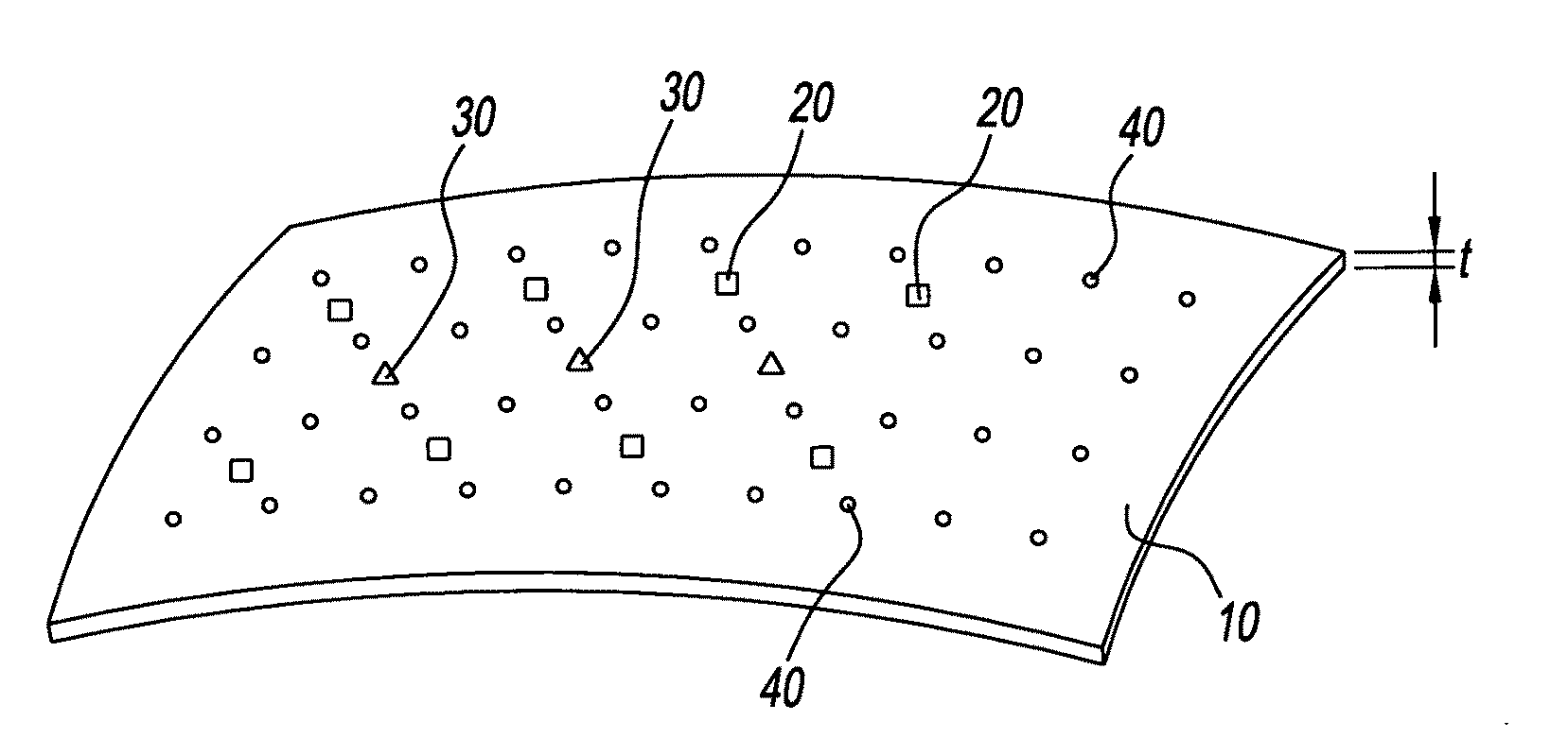
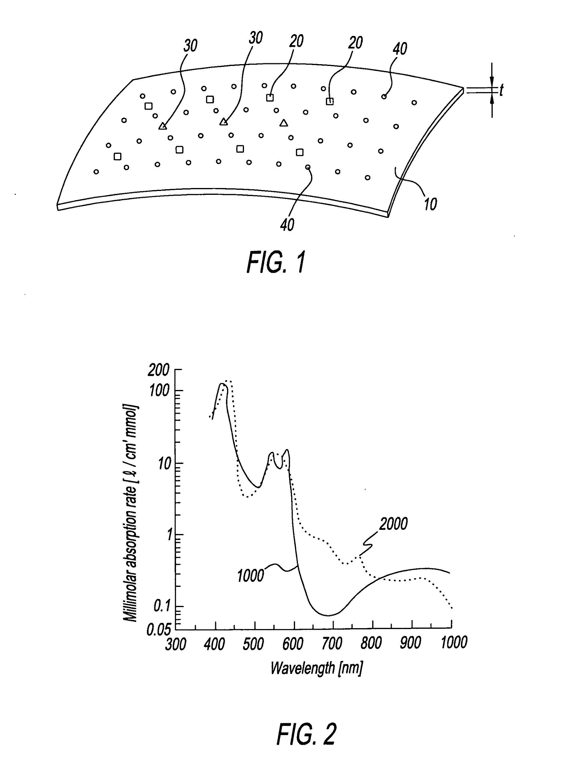
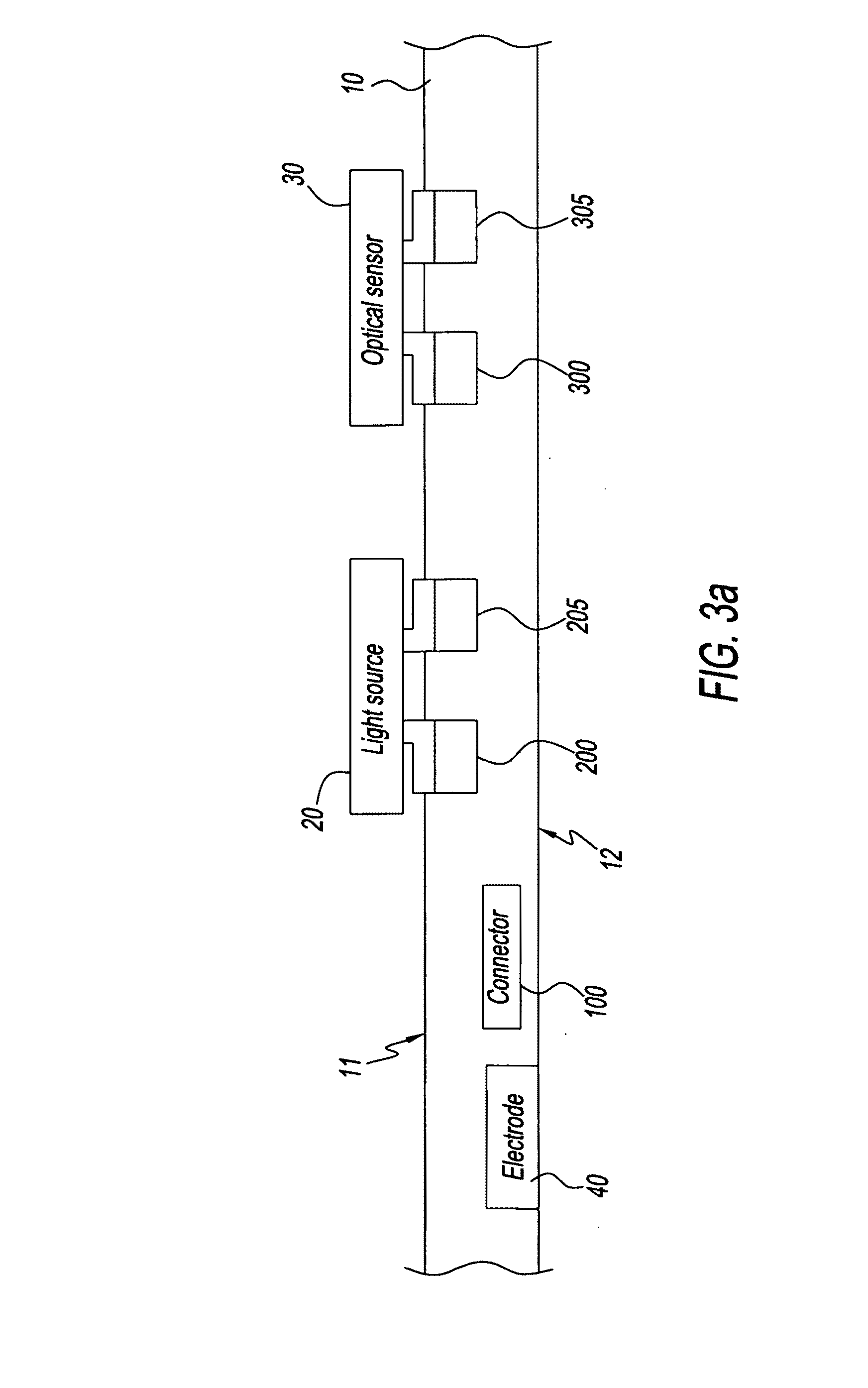
Disclosed embodiments relate to an apparatus for detecting brain conditions. The apparatus for detecting brain conditions may include: a layer which is located adjacent to the brain of a living body; a light source which is formed on the layer and irradiates light to the brain; and an optical sensor which is formed on the layer adjacent to the light source and detects the light scattered from the brain. Since detection is possible at a location relatively adjacent to the brain, the apparatus for detecting brain conditions may improve accuracy and reliability of detection. The apparatus for detecting brain conditions may be used to detect brain conditions such as cerebral oxygenation, cerebral blood volume, cerebral blood flow, etc. or to monitor brain activities, or to diagnose and / or localize the disease foci in case of neurovascular disease such as stroke including hemorrhage or bleeding, into or around the brain or brain tumors or epilepsy, etc. Since the apparatus for detecting brain conditions has a relatively flexible structure, damage to the brain tissue may be minimized.

Description

CROSS-REFERENCE TO RELATED APPLICATION[0001]This application claims priority to Korean Patent Application No. 10-2009-23156, filed on 2009 Mar. 18, and all the benefits accruing therefrom under 35 U.S.C. §119, the contents of which in its entirety are herein incorporated by reference.BACKGROUND[0002]1. Field[0003]Embodiments of the disclosure relate to an apparatus for detecting brain conditions.[0004]2. Description of the Related Art[0005]In the diagnosis of cerebrovascular diseases such as epilepsy, stroke or cerebral infarction and degenerative brain diseases such as dementia or Parkinson's disease, brain activities or cerebral oxygen saturation or cerebral blood parameters (hemoglobin concentrations, blood volume, blood flow, cerebral metabolic rate of oxygen, etc) may be used as indices. By continuously monitoring the brain activities or cerebral oxygen saturation or cerebral blood parameters, acutely occurring events may be detected or prevented. As a consequence, death or bra...

Claims


Application Information

Patent Timeline
IPC IPC(8): A61B6/00A61B5/0478A61B5/1459A61B5/296G01N21/17G01N21/35G01N21/359G01N21/47
CPCA61B5/0031A61B5/0084A61B5/0086A61B5/6868A61B5/4064A61B5/6814A61B5/14553A61B5/1455A61B5/14
Inventor CHOI, JEE HYUNSHIN, HEE SUPKIM, GUK BAESUNG, HOKUN
Owner KOREA INST OF SCI & TECH
Learn More