Oil storage structure for engine, engine incorporating same, and vehicle incorporating same

Inactive Publication Date: 2010-09-30
HONDA MOTOR CO LTD
View PDF6 Cites 3 Cited by
  • Summary
  • Abstract
  • Description
  • Claims
  • Application Information

AI Technical Summary

Benefits of technology

[0019]According to the first aspect of the present invention, the partition wall extending along the outer circumference of the clutch mechanism splits the space between the crankcase and the crankcase cover into the plurality of chambers, and the chamber not including the clutch mechanism is used as the oil storage chamber. Thus, since the clutch mechanism does not dip into oil, the disengagement performance of the clutch is ensured without affecting the clutch release performance.
[0020]In addition, since the oil storage chamber of the engine formed by the vertically split crankcase is formed only by the lower crankcase so as not to straddle the upper and lower crankcases, the amount of oil stored can be ensured at a maximum level, while ensuring liquid-tight performance of the oil storage chamber.
[0021]According to the second aspect of the present invention, the oil storage chamber is formed as the closed chamber by the partition wall avoiding the clutch mechanism, and the primary drive gear, and by merging the upper edge portion of the crankcase and the front wall and lower wall of the oil storage chamber. Therefore, the stored oil will not be stirred by the clutch and the drive gears. Thus, the bu

Problems solved by technology

This leads to a problem that the clutch dips into the oil.
Under conditions where a portion of the clutch constantly dips into oil, oil-separation performance between clutch plates lowers, which problematically affects the disengagement performance of the clutch.
If the o

Method used


Image

  • Oil storage structure for engine, engine incorporating same, and vehicle incorporating same
  • Oil storage structure for engine, engine incorporating same, and vehicle incorporating same
  • Oil storage structure for engine, engine incorporating same, and vehicle incorporating same

Examples


Embodiment Construction

[0034]An embodiment of the present invention will now be described, with reference to the drawings. Throughout this description, relative terms like “upper”, “lower”, “above”, “below”, “front”, “back”, and the like are used in reference to a vantage point of an operator of the vehicle, seated on the driver's seat and facing forward. It should be understood that these terms are used for purposes of illustration, and are not intended to limit the invention.

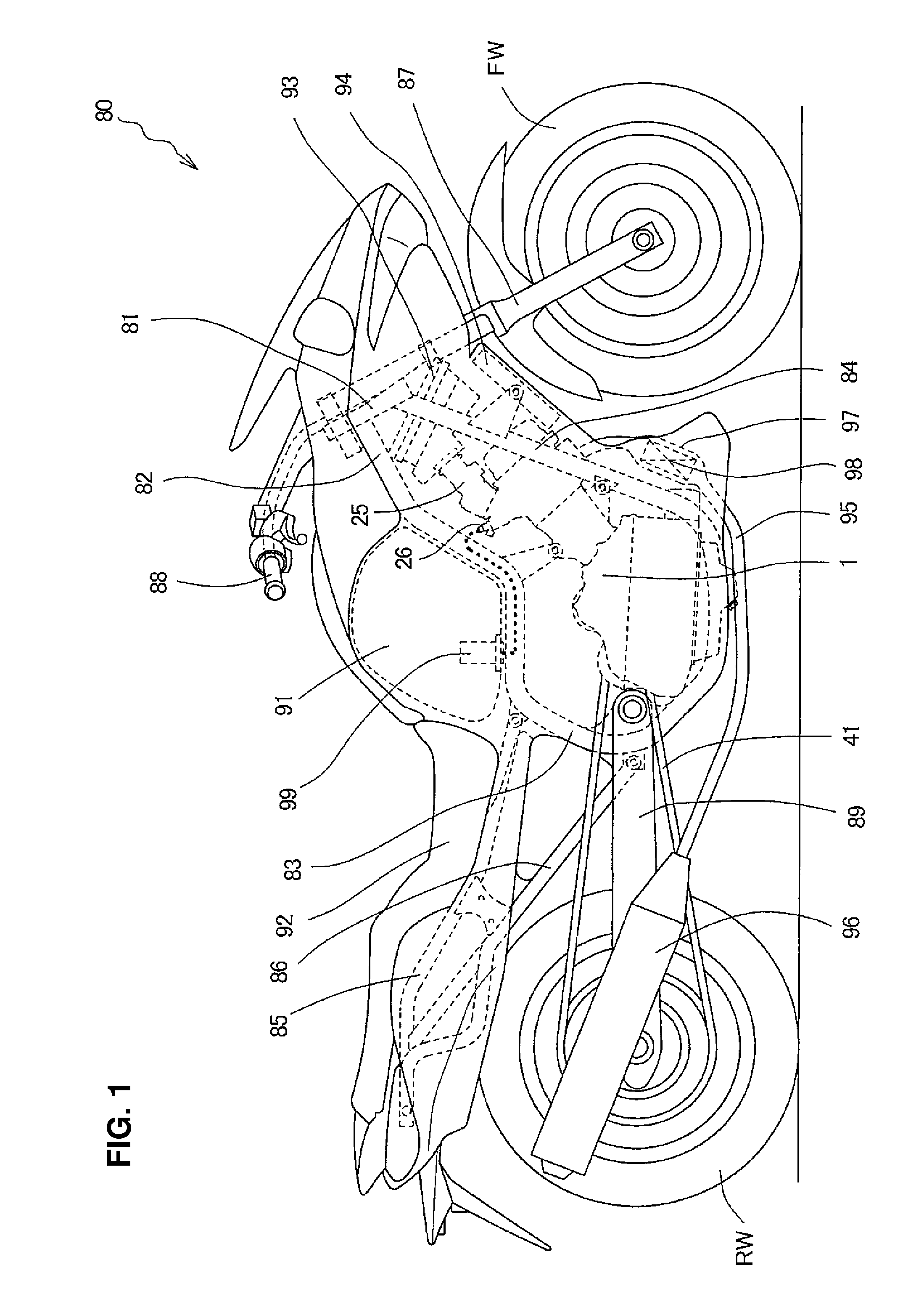
[0035]FIG. 1 is a lateral view of a motorcycle 80 according to an embodiment of the present invention. As shown in FIG. 1, a body frame of the motorcycle 80 includes a head pipe 81, main frames 82 extending obliquely rearward from the head pipe 81, and center frames 83 extending downward from the rear ends of the main frames 82.

[0036]The body frame of the motorcycle 80 further includes down frames 84 extending downward from the head pipe 81, seat stays 85 extending rearward from upper portions of the center frames 83, and mid frames...


PUM


Abstract

An internal combustion engine includes an oil storage structure defining an oil storage chamber provided for storing oil therein. The engine is configured such that a crankcase cover, covering a clutch mechanism, is joined to a crankcase for forming an oil storage chamber. The oil storage structure is applied to an engine having a vertically split crankcase, and is configured to prevent the clutch mechanism from dipping into stored oil so that clutch disengagement performance is not affected, and reliability of the liquid-tight sealing performance is extended. The crankcase cover is formed with a partition wall extending along the outer circumference of the clutch mechanism. The partition wall splits a space between the crankcase and the crankcase cover into two chambers. Of these chambers, a chamber separate from a clutch mechanism is used as the oil storage chamber, which is formed only by a lower crankcase and the crankcase cover.

Description

CROSS-REFERENCE TO RELATED APPLICATIONS[0001]The present invention claims priority under 35 USC 119 based on Japanese patent application No. 2009-087453, filed on Mar. 31, 2009. The entire subject matter of this priority document, including the specification, claims and drawings thereof, is incorporated by reference herein.BACKGROUND OF THE INVENTION[0002]1. Field of the Invention[0003]The present invention relates to an oil storage structure for a small-sized vehicle engine, and to an engine and a vehicle incorporating the same. More particularly, the present invention relates to an oil storage structure including an oil storage chamber formed by a partition wall splitting a space between a crankcase and a crankcase cover of an engine, and to an engine and a vehicle incorporating the same.[0004]2. Description of the Background Art[0005]There are known conventional engines, in which a crankshaft chamber is isolated from a transmission chamber, and an oil pump (scavenging pump) is ad...

Claims


Application Information

Patent Timeline
IPC IPC(8): F02B77/00F01M11/00
CPCF01M11/0004F01M2001/123F01M2011/0037F02B61/02F02F7/0039F16H57/029F16H2057/02065F16H57/04F16H57/0441F16H57/045F16H57/0494F16H2057/0203F16H57/031
Inventor NEGORO, MASAAKITADOKORO, HIROSHIOSUKA, TAKANORI
Owner HONDA MOTOR CO LTD
Why Eureka
Try Eureka