Plasma processing apparatus

a processing apparatus and plasma technology, applied in the field of high frequency antennas, can solve the problems of deteriorating plasma process uniformity more difficult to achieve plasma uniformity, so as to improve the uniformity of plasma density and plasma processing characteristics in the target object surfa

Inactive Publication Date: 2010-09-30
TOKYO ELECTRON LTD
View PDF11 Cites 28 Cited by
  • Summary
  • Abstract
  • Description
  • Claims
  • Application Information

AI Technical Summary

Benefits of technology

[0008]In view of the foregoing, the present disclosure provides a plasma processing apparatus capable of improving uniformity of plasma density and plasma processing characteristics in the target object surface.
[0010]In accordance with this configuration, the high frequency antenna includes the outer coil, the inner coil and the n (n is an integer equal to or greater than 1) number of intermediate coils between them that are concentrically wound about the central axis. As a result, plasma can be generated in a plasma excitation region by the n (n≧1) number of intermediate coils as well as the inner coil and the outer coil. Accordingly, it is possible to avoid a decrease of a plasma density, which would occur in an intermediate region between the inner and the outer coils if the plasma is generated by the two coils, i.e., the inner and outer coils. Therefore, overall plasma uniformity can be achieved, so that uniformity of the plasma process in the target object surface can be secured.
[0014]As a consequence, a plasma density at an outer region of the plasma excitation region is controlled to be slightly higher than an overall plasma density, while a plasma density decreases at an intermediate region between the outer region and the inner region of the plasma excitation region is suppressed. Therefore, the overall plasma uniformity can be achieved, so that the uniformity of the plasma process in the target object surface can be secured.
[0029]In accordance with the present disclosure, uniformity of plasma density and plasma processing characteristics in the target object surface can be improved.

Problems solved by technology

As a result, plasma process uniformity in a target object surface deteriorates.
Besides, since the plasma density also varies depending on plasma conditions such as pressure or the like, it has been difficult to achieve plasma uniformity.
Therefore, it has been more difficult to achieve the plasma uniformity.

Method used


Image

  • Plasma processing apparatus
  • Plasma processing apparatus
  • Plasma processing apparatus

Examples


first embodiment

Overall Configuration of Plasma Processing Apparatus

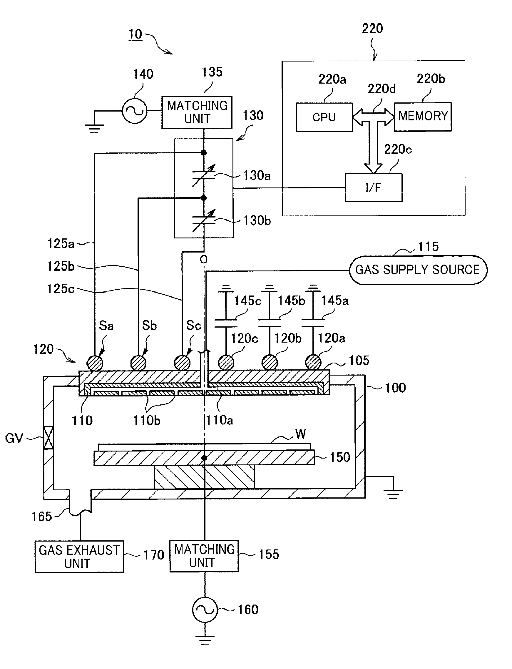
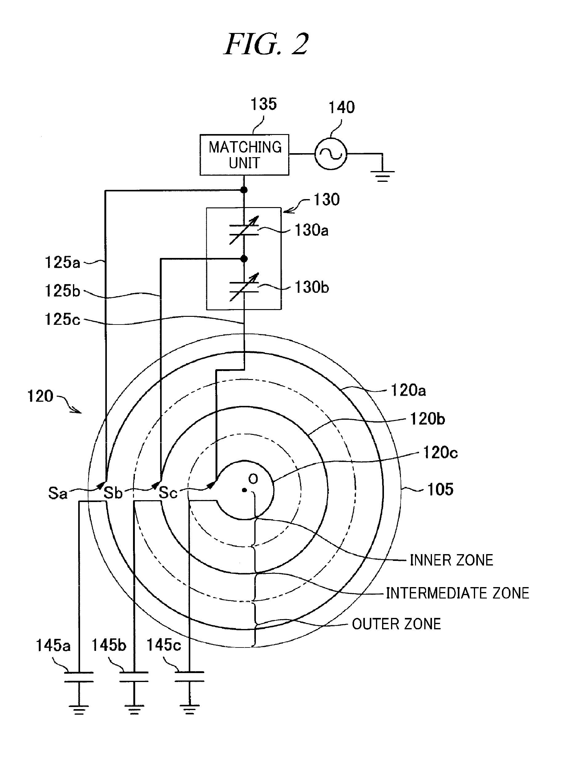
[0045]Referring to FIGS. 1 and 2, an overall configuration of a plasma processing apparatus in accordance with a first embodiment of the present disclosure will be explained. FIG. 1 is a schematic longitudinal cross sectional view of an inductively coupled plasma processing apparatus, and FIG. 2 is a diagram illustrating a configuration of a high frequency antenna.

[0046]As shown in FIG. 1, a plasma processing apparatus 10 such as an etching apparatus includes a processing chamber 100 for plasma-processing a wafer W which is loaded through a gate valve GV. The processing chamber 100 having a cylindrical shape is made of metal such as aluminum, and is grounded. An inner wall of the processing chamber 100 is anodically oxidized. Further, the inner wall of the processing chamber 100 may be covered with a dielectric material such as quartz, yttria, or the like.

[0047]A dielectric window 105 is fitted into an opening of the processing cha...

modification examples

of the First Embodiment

[0081]Modification examples of the first embodiment are illustrated in FIGS. 5 to 7. Although the inside configuration of a processing chamber 100 is not illustrated in each plasma processing apparatus 10 shown in FIGS. 5 to 7, the inside configuration of the processing chamber 100 is the same as shown in FIG. 1. In a plasma processing apparatus 10 of FIG. 5, a power feed point Sc of an inner coil 120c is deviated about 180° from power feed points Sa and Sb of an outer coil 120a and an intermediate coil 120b, respectively. In a plasma processing apparatus 10 of FIG. 6, power feed points Sb and Sc of an intermediate coil 120b and an inner coil 120c are deviated about 180° from a power feed point Sa of an outer coil 120a.

[0082]In a plasma processing apparatus 10 of FIG. 7, a power feed point Sc of an inner coil 120c is deviated about 180° from power feed points Sa and Sb of an outer coil 120a and an intermediate coil 120b, respectively. Here, the variable imped...

second embodiment

[0084]Generally, in the inductively coupled plasma processing apparatus, not only (1) the generation of the plasma by acceleration of electrons using the electromagnetic field energy from the high frequency antenna 120 needs to be considered, but (2) plasma uniformity also needs to be achieved in consideration of electrons coupled to the plasma by a capacitor. Thus, the apparatus needs to be designed in consideration of not only an antenna design for (1) but also a capacitive component for (2).

[0085]In the plasma processing apparatus 10 in accordance with the first embodiment, uniformity of a plasma density in a diametric direction of the wafer W can be achieved. That is, in the first embodiment, the high frequency antenna 120 is divided into the three imaginary zones, i.e., the outer zone, the inner zone and the intermediate zone, and the above-mentioned coils are installed in the respective zones in consideration of (1), so that the uniformity of the plasma density in the diametri...


PUM

PropertyMeasurementUnit
frequencyaaaaaaaaaa
frequencyaaaaaaaaaa
diameteraaaaaaaaaa

Abstract

A uniformity of plasma density in a target object surface and plasma processing characteristics can be improved. A plasma processing apparatus 10 includes: a processing chamber 100 in which a plasma process is performed on a wafer W; a first high frequency power supply 140 configured to output a high frequency power; a high frequency antenna 120 including an outer coil, an inner coil and n (n is an integer equal to or greater than 1) number of intermediate coil(s) that are concentrically wound about a central axis outside the processing chamber 100; and a dielectric window 105 provided at a part of a wall of the processing chamber 100 and configured to introduce electromagnetic field energy generated from the high frequency antenna 120 into the processing chamber 100.

Description

CROSS-REFERENCE TO RELATED APPLICATION[0001]This application claims the benefit of Japanese Patent Application No. 2009-0086470 filed on Mar. 31, 2009, and U.S. Provisional Application Ser. No. 61 / 186,921 filed on Jun. 15, 2009, the entire disclosures of which are incorporated herein by reference.FIELD OF THE INVENTION[0002]The present disclosure relates to a plasma processing apparatus performing a plasma process on a target object; and, more particularly, to a high frequency antenna to be used therein.BACKGROUND OF THE INVENTION[0003]As examples of apparatuses that perform microprocessing on a target object by exciting plasma, there are a capacitively coupled plasma processing apparatus, an inductively coupled plasma (ICP) processing apparatus, a microwave plasma processing apparatus, and the like. Among them, the ICP processing apparatus includes a high frequency antenna installed at a dielectric window provided on a ceiling surface of a processing chamber. In such an ICP process...

Claims


Application Information

Patent Timeline
Patent Type & Authority Applications(United States)
IPC IPC(8): C23F1/00
CPCH01J37/32091H01J37/321H01J37/32174H01J37/32935
Inventor KOSHIMIZU, CHISHIO
Owner TOKYO ELECTRON LTD
Why Eureka
Try Eureka