
Water phantom

Active Publication Date: 2010-09-30
ION BEAM APPL
View PDF8 Cites 11 Cited by
  • Summary
  • Abstract
  • Description
  • Claims
  • Application Information

AI Technical Summary

Benefits of technology

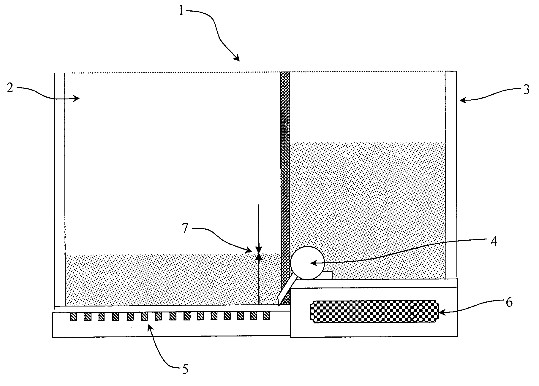
[0019]According to a first aspect of the present invention a water phantom for measuring and determining the dose distribution of radiation produced by a particle beam or photon radiation beam is provided. The water phantom comprises a water tank having a base, an acquisition detector and means for varying the water level in said water tank. The acquisition detector is a two-dimensional detector, preferably comprising a plurality of sensors for simultaneously measuring the dose in a plurality of points in an area, said area corresponding essentially to the base of the tank. This allows an easier and faster measure the dose distribution. Said detector is preferably attached or in a fixed relationship with the water tank and is positioned in a position related to the tank opposite to the beam source. Namely, if said beam is a vertical beam irradiating the top of the water tank, the acquisition detector is located in a fixed position related to the tank under and beneath said water tank. Said detector being preferably positioned outside the water tank.
[0020]Furthermore, due to the absence of any mechanical positioning device of the detector and / or the sensor, the radiation field arriving at the acquisition detector is not disturbed by these means. Furthermore, the absence of mechanical positioning means obviously reduces costs.
[0030]According to a third aspect of the invention, there is provided a use of the device or method according to the invention for commissioning tests of a radiation therapy apparatus, thereby drastically reducing the time amount required.

Problems solved by technology

This procedure is time consuming, and moreover, depends on the stability of the beam characteristics among measurements.
In addition, this process cannot be applied to radiation delivery methods where collimators are moved while irradiating, such as the virtual wedge method or IMRT.
This can be a problem, especially when using ionisation chambers as sensors.
Though the use of such a phantom is an established standard since many years, the handling of these large scanning water phantoms is cumbersome and time consuming.
This document presents some drawbacks as follows: the 3D scanning allows the measurement of one point in space at a time, which requires several days for complete TPS commissioning tests; moreover, due to the large water volume, phantoms are coupled to a moveable water tank and are mounted on a moveable support table.
Owing to their weight, they cannot be positioned on the patient couch.
Nevertheless this water phantom presents the same drawbacks of the water phantoms discussed herein above in that a time consuming process of displacements and measurements is needed, and that the measurement of time-dependent radiations fields such as the virtual wedge method or IMRT is not possible.
As a consequence, this water phantom is time consuming and needs several days for complete TPS commissioning tests.
However, such a device has some drawbacks as follows:the response of the scintillator to radiations is strongly dependent on energy of the radiation beam and therefore is not sufficient for quality requirements;Cerenkov radiations emitted from water traversed by radiations would strongly interfere with measurements;the use of mechanical means, which are required for moving the scintillator within the water tank, make the measurements process time consuming;it is not possible to perform source to surface distance measurements (SAD measurements).
However, all above-discussed water phantoms cannot provide measurements of time-dependent fields, since scanning detectors measure said radiation fields at different times. Moreover, it is not possible to perform measurements in a shallow depth (for example less than 1 cm).

Method used


Image

  • Water phantom
  • Water phantom
  • Water phantom

Examples


Embodiment Construction

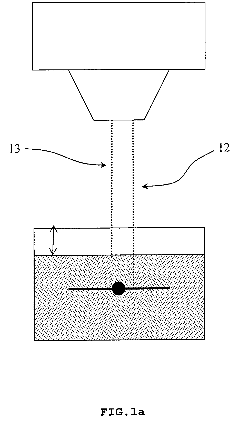
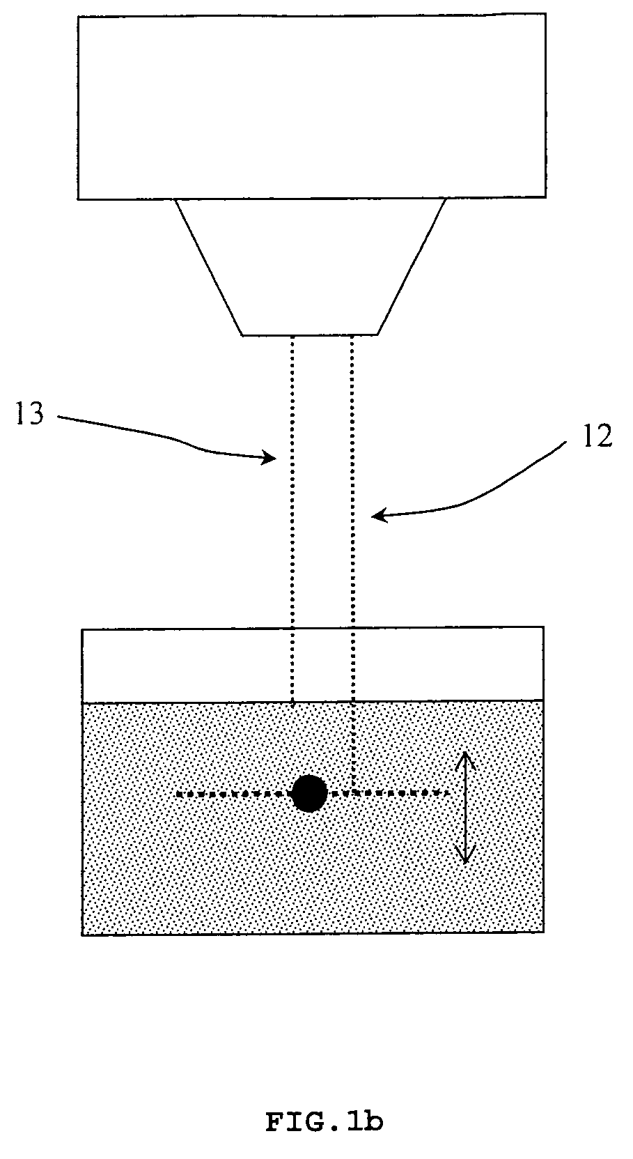
[0035]FIGS. 1a and 1b represent the principle of measurement made in two different configurations. In said figures, the tank is positioned essentially on a horizontal plane while the incident beam is irradiating the top of said tank, essentially according to a vertical axis. Namely, FIG. 1a is representing the TPR (Tissue to Phantom Ratio) or SAD (source acquisition distance) configuration, where the source-to-detector distance is fixed as the source-to-water phantom surface distance varies, while FIG. 1b is representing the DD (Depth-Dose) or SSD (source to surface distance) configuration, where the source-to-water phantom surface distance is kept constant as the source-to-detector distance varies.

[0036]Embodiments of the invention described hereinafter present the following features:[0037]1. Measurements of the radiation dose can be performed in either SAD or SSD configuration;[0038]2. Instead of taking a set of measurements using a scanning device, a plurality of sensors takes on...


PUM


Abstract

The present invention is related to a water phantom for measuring and determining the dose distribution of radiation produced by a particle beam or photon radiation beam comprising: a water tank; means for varying the water level in said water tank; an acquisition detector positioned in a fixed position related to the water tank opposite to the beam, wherein said acquisition detector is a two dimensional detector comprising a plurality of sensors and capable of simultaneously measuring the dose in a plurality of points in an area. Subsequent measurements are performed varying each time the water level within the water tank, until the dose distribution in the entire volume of the water tank is obtained.

Description

FIELD OF THE INVENTION[0001]The present invention is related to a water phantom for measuring and checking the dose distribution of a particle beam or photon radiation beam produced by a radiation therapy apparatus.STATE OF THE ART[0002]Water phantoms are used in radiation therapy for acceptance testing, commissioning and quality assurance (QA) measurements. Acceptance tests are detailed test procedures, performed normally once in the lifetime of a radiation therapy apparatus, in the factory, in order to assure the validity of the specifications of the radiation therapy apparatus, and to verify that the final deliverable meets the client's requirements and agreements. Commissioning tests of radiation therapy treatment planning systems (TPS) comprise a series of tasks which require an extensive set of measurements of radiation dose profiles. By using these data specific to a radiation therapy apparatus, the TPS can be tuned to deliver the required dose and dose distribution. Commissi...

Claims


Application Information

Patent Timeline
IPC IPC(8): G01T1/02G01T7/00G12B13/00G01T1/185
CPCG01T1/169A61B6/583
Inventor PLOMPEN, ROBMULLER, LUTZ
Owner ION BEAM APPL
Learn More