
Enhanced light detector for computed radiography

a computed radiography and enhanced light technology, applied in the field of computed radiography, can solve the problems of difficult to improve image quality beyond a certain point, and high noise sensitivity, so as to achieve the effect of improving signal-to-noise performan

Inactive Publication Date: 2010-09-30
CARESTREAM HEALTH INC
View PDF3 Cites 11 Cited by
  • Summary
  • Abstract
  • Description
  • Claims
  • Application Information

AI Technical Summary

Benefits of technology

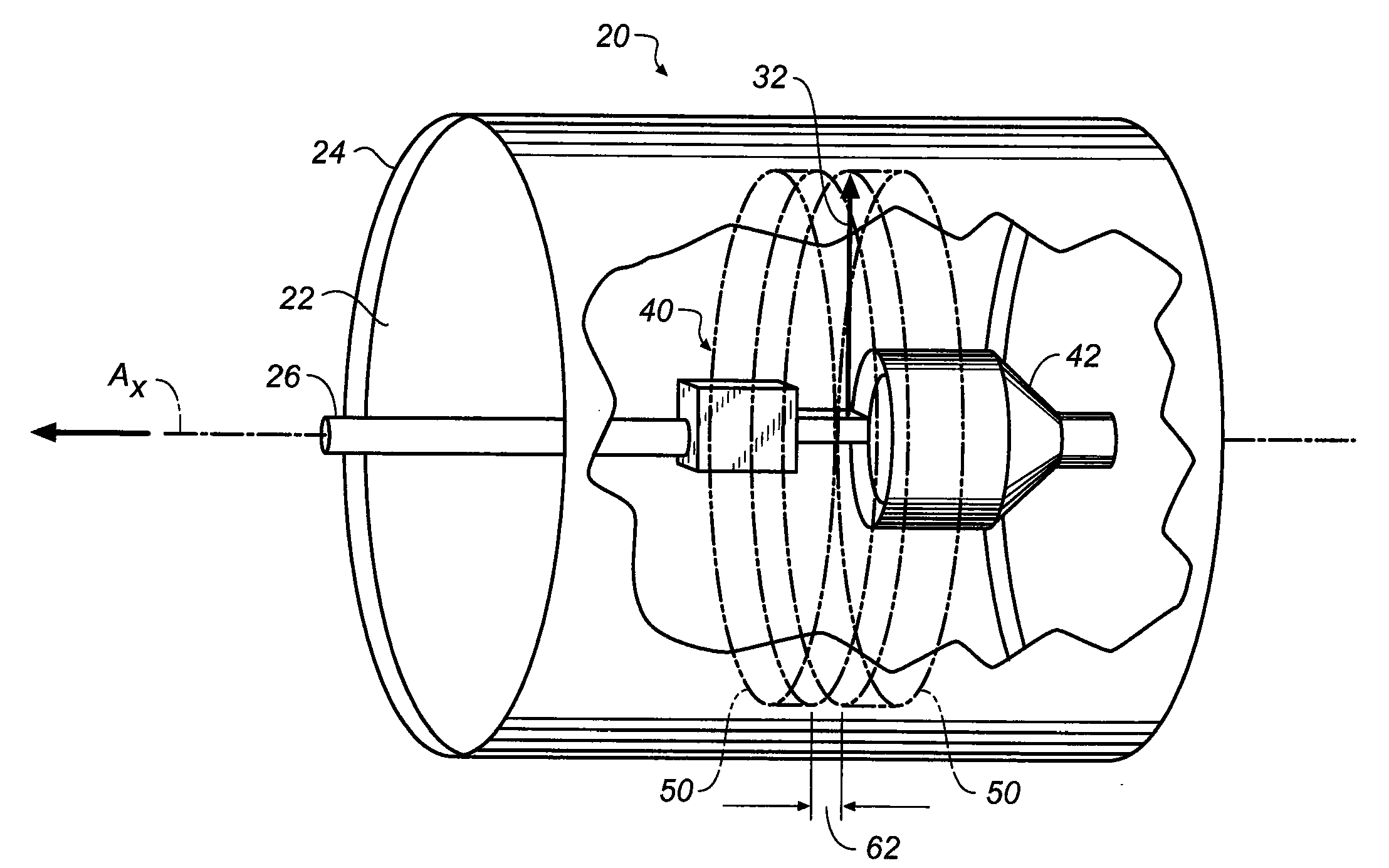
[0009]Embodiments of the present invention can provide improved signal-to-noise performance of an internal drum CR scanner over earlier designs.

Problems solved by technology

While conventional CR scanning methods have achieved some level of success, it has proven difficult to improve image quality beyond a certain point.
One innate difficulty relates to the relative inefficiency of the phosphor material itself.
Due to low efficiency levels, the photomultiplier tube (PMT) or other detector must be very sensitive in order to capture the image signal and is thus highly susceptible to noise.
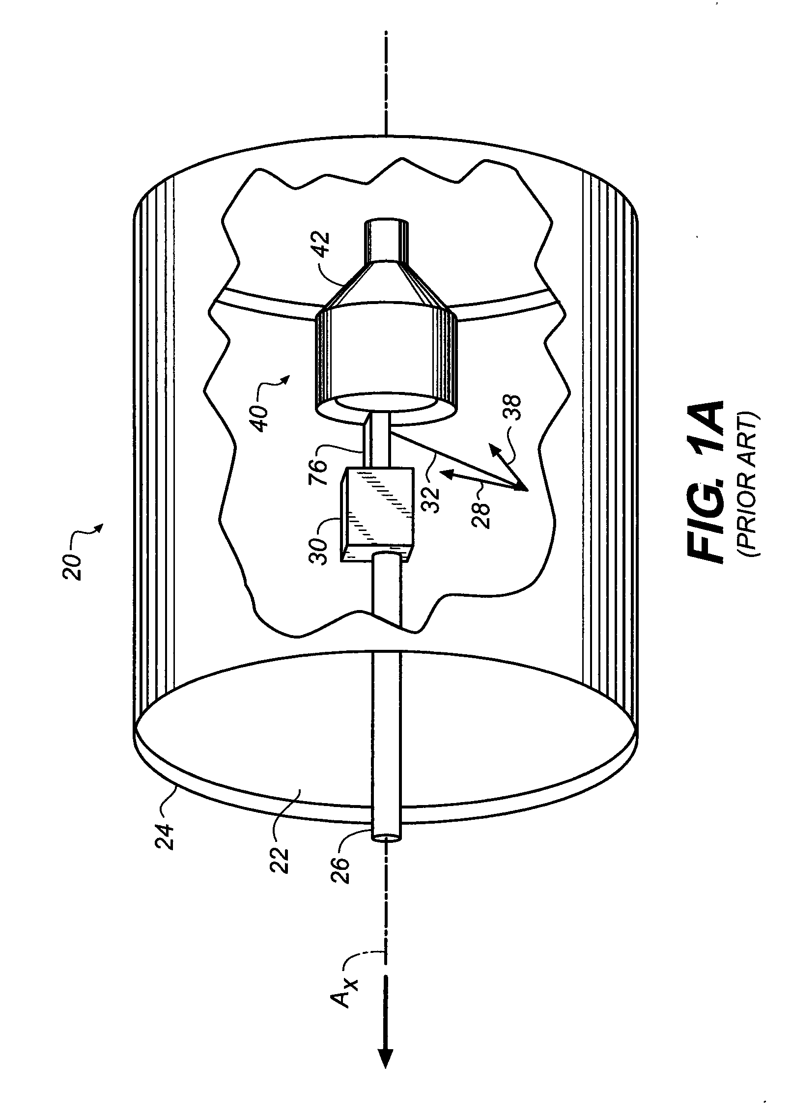
However, because of its cylindrical geometry, this type of scanner can be subject to a false signal, termed “flare”.
This stray light, traveling inside the drum, can impinge on other portions of the phosphor sheet, inadvertently causing emission from areas other than the stimulated spot or pixel.
Flare degrades collection efficiency in two ways: exciting a false signal by premature emission from areas of the surface outside the scanned spot and draining stored energy due to such emission in portions of the phosphor that have not yet been scanned.
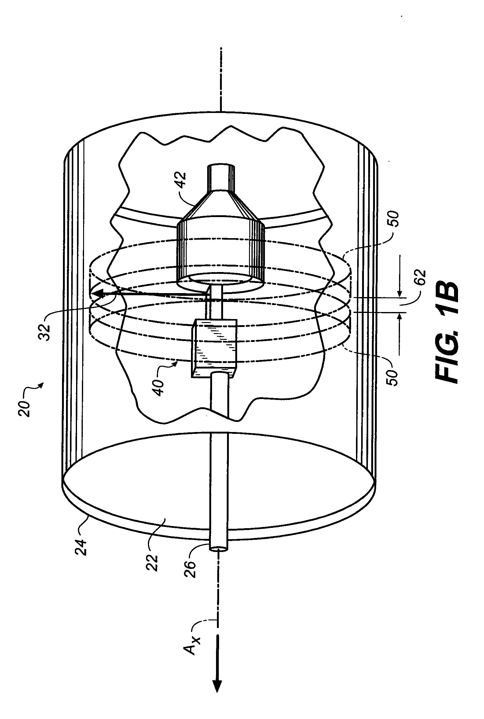
However, this type of approach can also restrict the amount of stimulated light that is able to enter the collector from the spot being scanned.
As a consequence, providing a suitable slot width generally involves a compromise that tolerates more flare than is desired and achieves less collection efficiency than is desired.

Method used


Image

  • Enhanced light detector for computed radiography
  • Enhanced light detector for computed radiography
  • Enhanced light detector for computed radiography

Examples


Embodiment Construction

[0029]The following is a detailed description of the preferred embodiments of the invention, reference being made to the drawings in which the same reference numerals identify the same elements of structure in each of the several figures.

[0030]Figures shown and described herein are provided in order to illustrate key principles of operation according to the present invention. Some exaggeration of relative dimensions and scale may be necessary in order to emphasize basic positional and structural relationships or principles of operation.

[0031]In the context of the present disclosure, a shape is substantially rectangular if its sides are orthogonal to one another to within at least 8 degrees. A filter is substantially transmissive to light of a given wavelength if it is considered to be at least 80 percent transmissive to light of that wavelength, preferably at least about 85 percent transmissive or better. An element is substantially opaque to light of a particular wavelength if it i...


PUM


Abstract

A scanning apparatus for obtaining an image from a phosphor sheet has a cylindrical drum having an inner axis and having an inner surface that is concave with respect to the axis. A light collector is coupled to a transport mechanism that is actuable to translate the light collector along a direction parallel to the axis. The light collector has a beam generator with a light source and a rotatable beam deflector that is actuable to provide a rotating scanning beam. There are first and second cylindrical hoops circumferentially disposed about the axis and spaced apart from each other along the direction of the axis to define a slot aligned with the rotating scanning beam as it scans the phosphor sheet. At least one light detector is disposed to detect light stimulated from the phosphor sheet by the scanning beam.

Description

FIELD OF THE INVENTION[0001]The invention relates generally to computed radiography (CR) apparatus for obtaining an image stored on a photostimulable medium and more particularly relates to an apparatus and method for enhancing detection of the stored image signal and suppressing image flare in a scanning apparatus.BACKGROUND OF THE INVENTION[0002]In Computed Radiography (CR), a phosphor sheet is exposed to x-ray or other short-wavelength ionizing radiation and stores a latent image that is read out by a scanning device. Within the scanning device, read-out is effected by illuminating the sheet, one spot or pixel (picture element) at a time, with a stimulating beam of a first relatively long-wavelength light, such as with red laser light. When it receives the stimulating beam, the illuminated spot on the phosphor sheet emits radiation at a second, shorter wavelength, typically in the blue region. The amount of radiation that is emitted upon stimulation is proportional to the amount ...

Claims


Application Information

Patent Timeline
Patent Type & Authority Applications(United States)
IPC IPC(8): G03B42/08
CPCG02B7/1821G02B26/105H04N1/0642H04N1/0607H04N1/0635G03B42/08
Inventor BOUTET, JOHN C.MUIR, CHRISTOPHER M.NEWMAN, PETER A.
Owner CARESTREAM HEALTH INC
Learn More